About the IS200AEAAH1CPR1
The IS200AEAAH1CPR1 is a GE PCB designed as a component printed circuit board for insertion in the Mark VI series' automated drive assembly. The Mark VI is part of the Speedtronic series for gas/steam heavy-duty turbine management. This series has been in use since GE released the first of the Speedtronic systems (Mark I) in the late 1960s. The Mark VI used the most advanced technology available at the time of its release and includes a Windows-based PC operator interface. The Mark VI is also designed around GE proprietary software like CIMPLICITY graphics and the GE Control System Toolbox, which is used for maintenance. The Mark VI Turbine Control System Series containing this IS200AEAAH1CPR1 PCB product here has to be considered quite the significant functional upgrade upon the Mark V Turbine Control System Series of the same full extended series name essentially, as the Mark VI Series tacked the more alternative energy-guided wind turbine possible functional application onto the gas and steam settings established with the rollout of the Mark V here.
Hardware Tips and Specifications
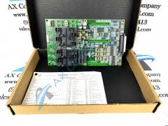
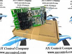
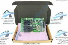
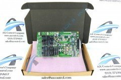
The IS200AEAAH1CPR1 has three terminal strips. These are placed parallel to each other on the surface of the board. Each strip has twelve positions. The board has a female jack connector located along its right edge. This is a right-angled connector. There is also a 2-position female connector (J4) located along the top edge. The board has a three-pin vertical male pin connector located along the top edge. This is labeled P18. The IS200AEAAH1CPR1 has sixteen vertical metal connectors. Eight of these are located along the left edge of the board. These are labeled P1 through P8. P10 through P17 are located in two boxes on the top edge of the board, with the even connectors located in one box and the odd in another. The IS200AEAAH1CPR1 has eight relays. These are marked K1 through K8. They are located on the board in two blocks of four. Two heat sinks are located next to these components. Directly below the heatsinks there are three large wire wound resistors. The board has an additional 200+ resistors of other types. It also has various capacitors and diodes, as well as over forty integrated circuits. We suggest following installation guidelines as written in manuals or data sheets supplied by the original manufacturer.
Unluckily enough for the sake of this IS200AEAAH1CPR1 personalized product page here, this IS200AEAAH1CPR1 device is not well-contextualized within a great quantity of originally-produced instructional manual materials on the internet, which means that any IS200AEAAH1CPR1 details included above is reminiscent primarily of a diligent visual inspection of the IS200AEAAH1CPR1 PCB itself. One other decent supplementary source of IS200AEAAH1CPR1 Board hardware information can be sourced as its IS200AEAAH1CPR1 functional product number, which was actually specifically designed by the trusted automated industrial manufacturer to indirectly display a number of relevant IS200AEAAH1CPR1 Board hardware details through a series of consecutive functional naming chunks. For example, the IS200AEAAH1CPR1 product number begins with an iteration of the dual-functioning IS200 series tag demonstrating this IS200AEAAH1CPR1 product's normal Mark VI Series assembly version as well as its domestic original location of GE manufacture. Some of the other important IS200AEAAH1CPR1 Board details revealed in this fashion include the IS200AEAAH1CPR1 PCB's:
- AEAA functional product acronym
- Group one Mark VI Series grouping
- Conformal PCB coating style
- Three-fold revision history


