About the IS200BAIAH1B
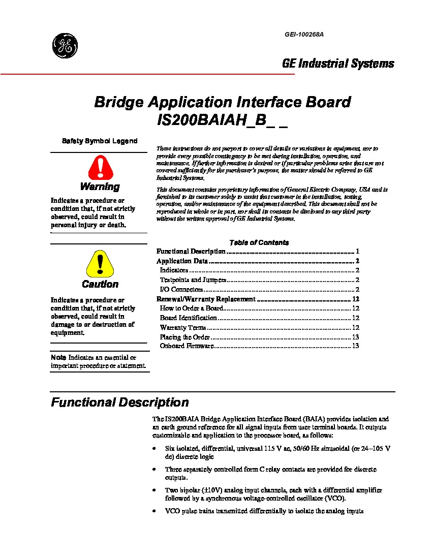
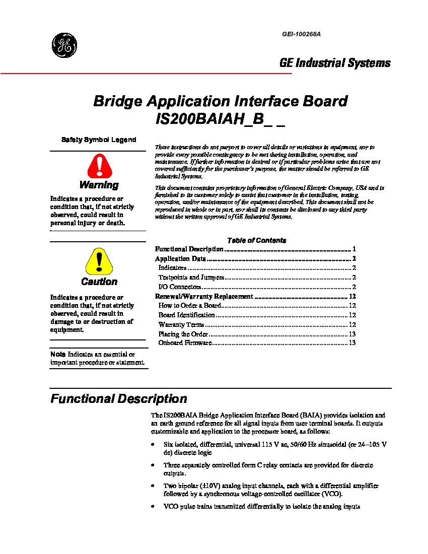
The IS200BAIAH1B is designed to function as a bridge application interface board in Innovation Series Drive Systems. This board provides earth-ground reference and isolation for signal inputs from terminal boards. Each board is designed with an onboard EEPROM containing firmware not intended for removal or field programming. The Innovation Series that this particular IS200BAIAH1B Bridge Application Interface Board printed circuit board product offering belongs to has to be considered a child product series of the greater Mark VI Turbine Control System Series that this IS200BAIAH1B PCB was originally devised for. This IS200BAIAH1B Bridge Application Interface Board's greater Mark VI Turbine Control System Series, as you have more than likely been able to tell based off of its full extended series name, has a set of specific functional applications in the control systems and management system of popular General Electric-compatible gas, wind, and steam turbine automated assemblies. This is quite the upgrade upon the previously-developed Mark V Turbine Control System Series, as the Mark V Series possesses a more restricted set of possible applications in gas and steam-centered settings alone.
Hardware Tips and Specifications
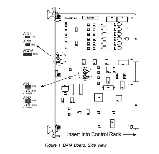
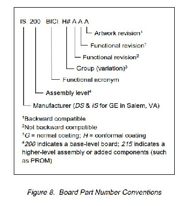
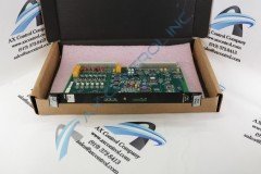
The IS200BAIAH1B is built with a narrow black front panel. This panel includes a single green LED that is marked “IMOK.” The panel also carries the board number and the warning “Install in Slot 1 only.” The IS200BAIAH1B is an Innovation series board, which is designed to be placed into a specific rack slot. This board can be damaged if it is installed into the improper rack slot. Because of this damage risk, it is important too to consider PCB dimensions before making a purchase decision. This particular printed circuit board comes revised with roughly-measured dimensions of 12 inches lengthwise by 9 inches wide. The thickness of this PCB is no greater than an inch and a half. The IS200BAIAH1B has three relays, six varistors, four jumper switches, three test points, and several integrated circuits. The board has two backplane connectors located on one edge. These backplane connectors are labeled as Pancon 106-128-023 connectors, which have a generally low market availability. Jumpers should be placed in either the VIN position or the 4-20 mA position. The aforementioned black front panel of the IS200BAIAH1B printed circuit board has openings in two central positions, allowing for user access of board parts labeled TP1 TP2 and TP3; three different available testing points. A number of designations printed on the face of the IS200BAIAH1B may provide the prospective buyer with clues into specifications, as online manual information for this circuit board is extremely limited. Some of the general printed labels visible on the base plate of this PCB include:
- IS200BAIAH1
- BAIA#B 6DA02
- PVC-3 1598
- T50
- F36
A wrist grounding strap should be worn at all times when handling the IS200BAIAH1B, considering this board's extreme sensitivity to static electricity. Our team will use an anti-static wrap to protect the IS200BAIAH1B during transit. Please follow all installation procedures as written in manuals and data sheets from the manufacturer. If these have not been retained, refer to GE publication GEI-100268 for information. This IS200BAIAH1B Bridge Application Interface Board printed circuit board product offering from GE is actually not considered the originally-produced device of its specific GE Mark product series intended functionality; as in reality that would be the IS200BAIAH1 parent printed circuit board of the same functional description notably not utilizing this IS200BAIAH1B product's sole B-rated functional product revision.


