About the IS200BICLH1A
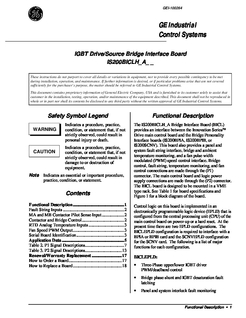
This IS200BICLH1A printed circuit board product offering was first designed and manufactured specifically for placement in automated industrial giant manufacturer General Electric's Mark VI Turbine Control System Series, as should have been mentioned in the IS200BICLH1A instructional manual materials and brief product description inserted above. This IS200BICLH1A device's Mark VI Series, as you can probably tell through analysis of its full series title, exists with a series of possible functional applications across a range of General Electric-compatible gas, steam, and even wind turbine functional settings. This must be highlighted as a stark functional improvement upon the Mark V Turbine Control System Series of years past, as the Mark V Series unfortunately only is applicable to gas and steam-based functional environments. This IS200BICLH1A device's Mark VI Series is also lauded in general for its status as one of the last-developed GE Mark product series to utilize the patented Speedtronic control system technology.
Hardware Tips and Specifications
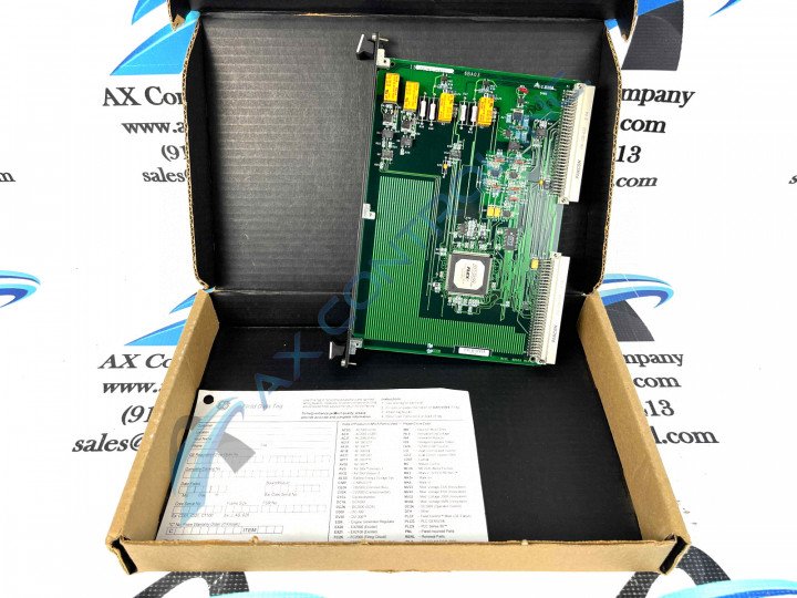
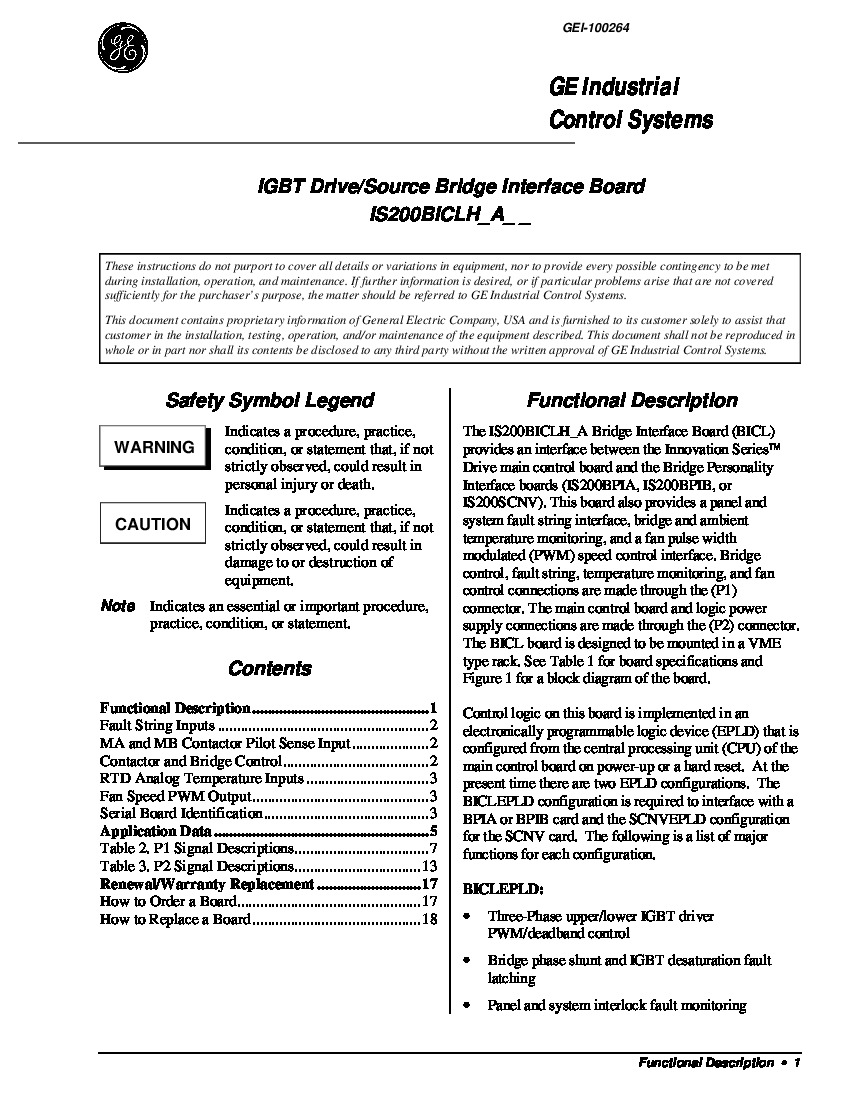
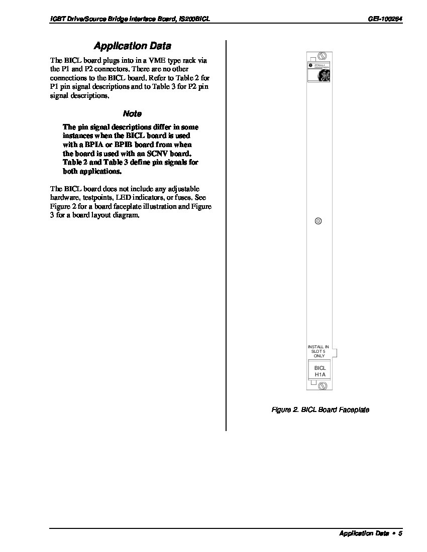
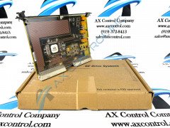
The IS200BICLH1A is an IGBT Drive/Source Bridge Interface Board (BICL) created by GE for the Innovation Series. The purpose of the IS200BICLH1A is to play a go-between an Innovation Series Drive and the Bridge Personality Interface Boards (BPIA, BPIB, or SCNV), being a primary interface between them. This board has the ability to monitor ambient and bridge temperatures. It has an interface with a PWM speed control and a system fault display. This board has a 1024-bit serial memory that is usually equipped with information about the board’s revision and identification. The IS200BICLH1A has a nearly blank faceplate with a label that has “Install in Slot 5 Only” written on it. There are two brackets on the faceplate that can help install and remove the card from a VME type rack. Next to the brackets are two screws that help to further secure the card to the rack. There are many internal components on the actual PCB though. There are 73 resistors, 31 capacitors, 3 diodes, 15 integrated circuits, 4 relays, a metal oxide varistor, and 3 transistors. On the right edge of the board are two P1 and P2 pin connectors that connect the IS200BICLH1A to a card rack assembly.
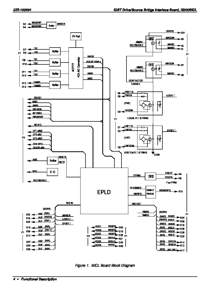
For more information about the IS200BICLH1A, please consult the datasheet GEI-100264. It is important to slide this board into the correct slot because if it is inserted into a different slot, the wrong connection can damage the board. Anti-static procedures should be followed while handling or trying to install this board. In terms of some of this IS200BICLH1A product's processing specifications, any control logic necessitated for the normative daily function of this IS200BICLH1A device is put into action through use of its sole electronically-programmable logic device or its EPLD. The main control board of this IS200BICLH1A product's greater Mark VI Series automated drive assembly pertains to the IS200BICLH1A PCB's EPLD device as is configured from the main central processing unit or CPU on this control board. Each one of this BICL-abbreviated configurations are described by a factory-printed nomenclature label beginning with a tag stating the Mark VI Series products they pertain to in an abbreviated form. The two configurations necessitated by this IS200BICLH1A device's EPLD are again described in the original instructional materials above as the:
- BICLEPLD configuration
- SCNVEPLD configuration


