About the IS200CABPG1B
The IS200CABPG1B is a device called a control assembly backplane board. This device is a PCB or printed circuit board that was made to be part of the Speedtronic Mark VI series which was made by GE or General Electric. The Mark VI is just one of many different series in General Electric’s Mark line. The Mark VI Turbine Control System Series is something of a well self-described General Electric Mark product series offering, given the fact that it exists with a set of specific functional application in General Electric-compatible gas, steam, and even wind turbine automated drive assemblies. With this being the case, the Mark VI Series containing this IS200CABPG1B component printed criticus board here has to be defined as a massive functional upgrade upon the Mark V Turbine Control System Series of the same name that immediately preceded it, as this eariler-developed GE Mark Series has a more restricted functional capacity in the control systems and management systems of General Electric-compatible gas and steam turbine assemblies alone.
Hardware Tips and Specifications
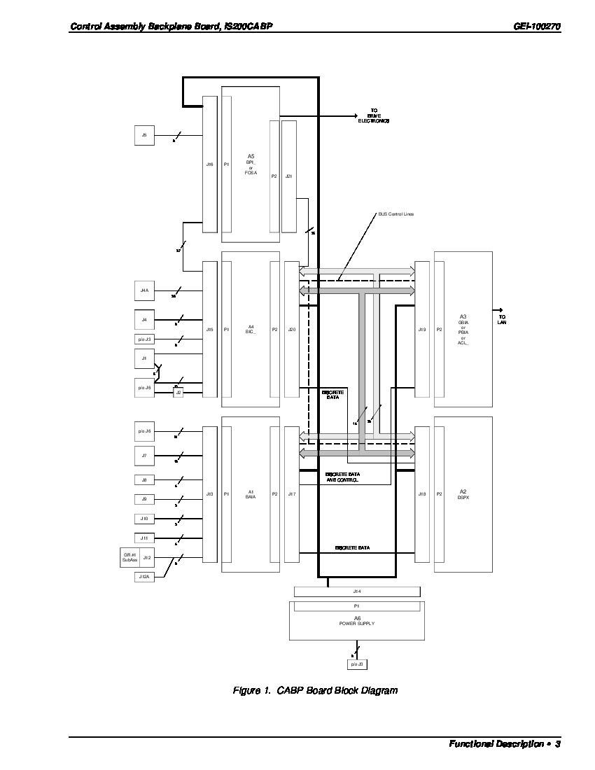
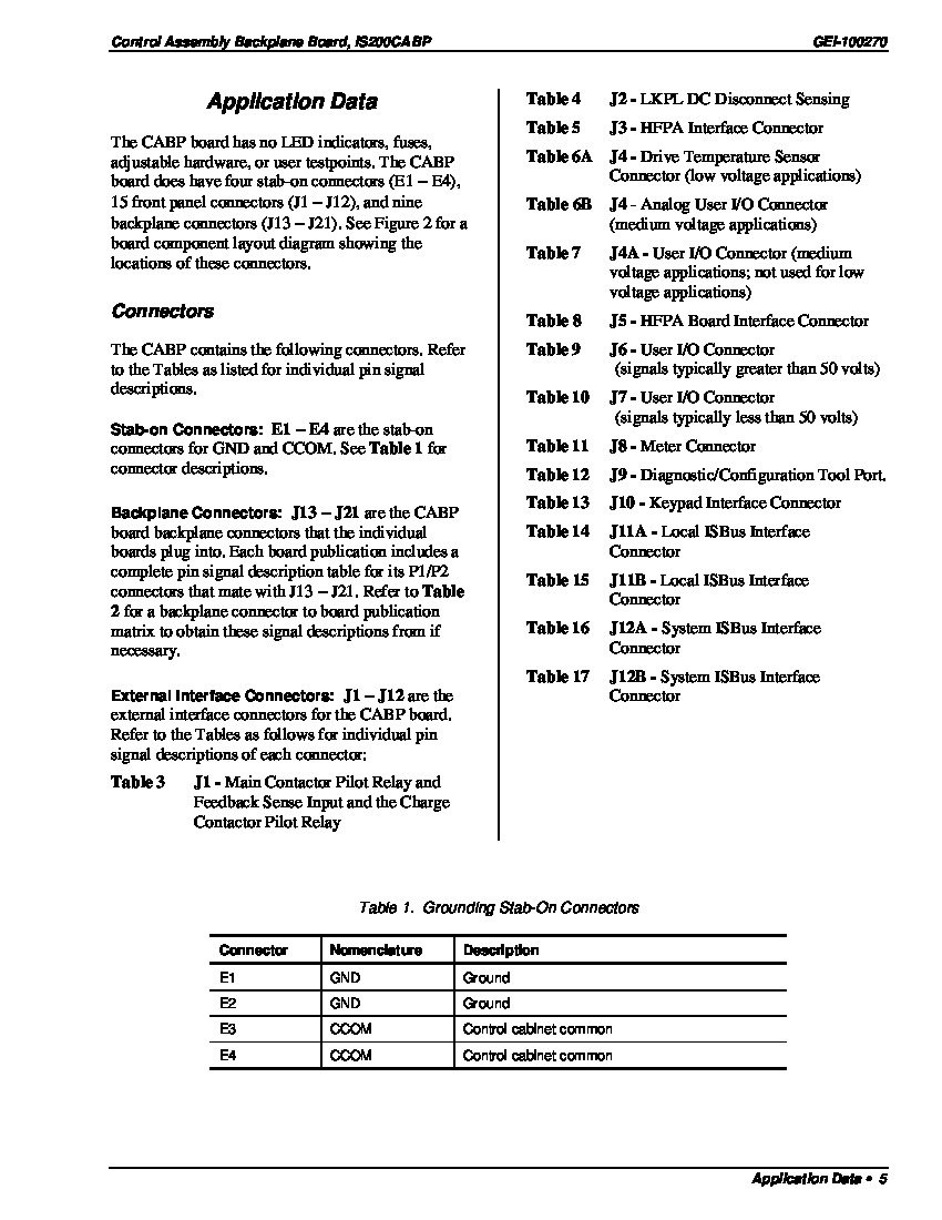
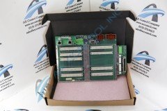
The IS200CABPG1B is a multi-layer printed wiring board. When printed wiring boards are inserted into the IS200CABPG1B, this device enables their connections. The IS200CABPG1B is an interface between external signals. Wiring boards such as the IS200RAPA, IS200DSPX, IS215GBIA, and IS200BAIA or others can be connected into the CABP board. The IS200CABPG1B gives connectors to different external interfaces such as user control I/O (input and output), meters for front panels, configuration and diagnostic tools, keypads for front panels, ports, inputs for power supply, and ports. The IS200CABPG1B features a range of connectors in varying sizes. Nine (9) long connector ports which are white are positioned on the IS200CABPG1B. Five (5) of these connector ports have been placed on the left while and the last four (4) are located on the right end. Four (4) connector ports are near the top border of the IS200CABPG1B. Two of these ports which are green are positioned at the upper left and the remaining two which are reddish-brown are at the upper right. On the right end of the IS200CABPG1B, one small part is connected to the PCB which has two (2) extra connector ports. One (1) of the ports is silver and metal and the other one is green.
While most of the above-stored IS200CABPG1B printed circuit board product offering hardware component and component specification information has been sourced from a visual inspection of the IS200CABPG1B printed circuit board or PCB for short itself, this IS200CABPG1B product does seem to be accompanied online by an uncharacteristically high amount of originally-printed instructional manual materials; including the IS200CABPG1B Datasheet attached above in our manuals tab for your convenience of research. According to this primary document, the IS200CABPG1B PCB here makes use of several different styles of Mark VI Series connectors; utilizing Stab-on, Backplane, and finally External Interface connector styles, with positionings and individual factory-printed nomenclatures labeled in detail. For example, this IS200CABPG1B printed circuit board's stab-on connectors include its E1 GND Ground Connector, the E2 GND Ground Connector, the E3 CCOM Control Cabinet Common Connector, and finally the E4 CCOM Control Cabinet Common Connector. Each of these listed connectors have been named through a combination of their GE-identified connector numbers, nomenclatures, and finally a basic functional description again as provided in originally-printed Mark VI Series instructional documentation. Connectors are not the only hardware element described in detail in this IS200CABPG1B device's manuals, as they seem to additionally indicate a set of specific installation practices including the standardized wearing of a wrist grounding strap.


