About the IS200CVMBG1A
This IS200CVMBG1A printed circuit board product offering or PCB for short from the trusted automated industrial giant manufacturer General Electric was specifically originally introduced with a specific functional placement in their Mark VI Turbine Control System Series in mind. The Mark VI Turbine Control System Series containing this IS200CVMBG1A product and many more, exists with a set of specific possible functional applications in the management and control systems of General Electric-compatible gas, steam, and wind turbine automated drive assemblies. This must be defined as a massively-significant functional upgrade upon the previous industry-standard Mark V Turbine Control System Series of almost the exact same series title, as the Mark V Series' established gas and steam-based possible functional environments were added onto by the alternative energy-based wind turbine possible functional application with the advent of the Mark VI Series.
Hardware Tips and Specifications
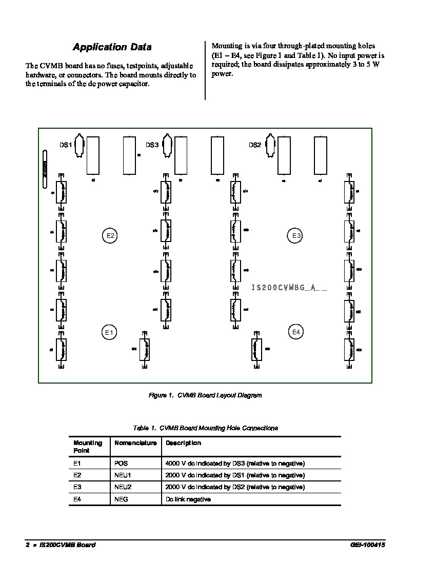
The IS200CVMBG1A is a device which is called a capacitor voltage monitoring board or CVMB. This is a form of printed circuit board or PCB. The IS200CVMBG1A is a component which monitors voltage across DC link capacitors within Innovation Series drives. Luckily enough for the research purposes of this IS200CVMBG1A personalized product page here, this IS200CVMBG1A product offering is well-contextualized online within an uncharacteristic wealth of originally-pertinent Mark VI Turbine Control System Series instructional manual materials. For instance, each of this IS200CVMBG1A device's various mounting hole connections are detailed in the IS200CVMBG1A Data Sheet made available to our manuals tab for your convenience of research just above, with individual connection being accompanied by their own respective factory-printed nomenclature label. Some of the CVMB mounting hole connections revealed in its datasheet include its:
- POS E1-Mounted 4000 V dc DS3 (relative to negative) Point
- NEU1 E2-Mounted 2000 V dc (relative to negative) Point
- NEU2 E3-Mounted 2000 V dc (relative to negative) Point
- NEG E4-Mounted Dc link negative Point
The IS200CVMBG1A gives turbine operators a secondary indication of the presence of voltage when the bridge cabinet doors are opened. This CVMB circuit board features three (3) small lamps which are neon labeled as DS3, DS2, and DS1. These are situated in a horizontal line along of top edge of the IS200CVMBG1A. They can be clearly seen when the doors of the bridge cabinet are opened. These small lamps blink whenever the DC bus contains high voltage of more than fifty (50) volts DC. These neon lamps are controlled by an attenuator network. Both bulb clips and bulbs may be replaced using parts with the numbers 68A944080P1 and 68A7804P4. No test points, fuses, connectors or adjustable hardware are featured on the IS200CVMBG1A. This board can be mounted right onto the DC power capacitor’s terminals with four (4) through-plate mounting holes which are labeled as E1, E2, E3, and E4. E2 and E1 are positioned on the left half of the printed circuit card and the E3 and E4 have been located on the PCB’s right half. The IS200CVMBG1A does not require any input power and dissipates approximately three (3) to five (5) watts of power. The IS200CVMBG1A is a large rectangular printed circuit board which features electronic components such as capacitors and resistors.


