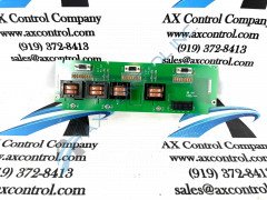
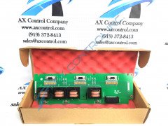
About the IS200EACFG2BAA
This IS200EACFG2BAA printed circuit board product offering from General Electric was originally designed and manufactured with a specific functional placement in the brand's Mark VI Turbine Control System Series automated drive assembly in mind, as would have been indicated above in the brief functional product description. The Mark VI Series that this IS200EACFG2BAA device is attributed to, as it is known in short, exists as quite the noteworthy functional improvement upon the previously-existing industry-standard Mark V Turbine Control System Series of a very similar full extended series title, as the Mark VI Series added the alternative energy-focused wind turbine possible functional environment to the gas and steam turbine-centered possible applications seen earlier on with the initial release of the Mark VI. This IS200EACFG2BAA printed circuit board product offering's greater Mark VI Series is also held in high esteem as a function of its quality as one of the final-developed GE Mark product series to incorporate the patented Speedtronic control system technology into a number of its product offerings.
Hardware Tips and Specifications
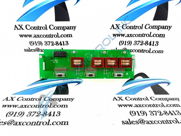
The IS200EACFG2BAA model is labeled as an Exciter ac Feedback Board produced by General Electric to work with models in the EX2100 or Mark VI series. This model will measure the exciter PPT ac supply voltage and currents. There are transformers on this model, which will be used for three-phase voltage measurement, with terminals used for control of the two Flux/Air core coils. The outputs produced by the current and voltage currents will be fanned out to the DB9 connectors; once the DB9 connectors have accepted the circuits they will be sent to the M1, M2, and C controllers. This is one of three versions of the EACF board. Each of the EACF boards is equipped with a different voltage; the voltage available on this model is 1000 V rms +20% at approximately 50/60 Hertz (Hz). Along with the T1 through T4 transformers on the IS200EACFG2BAA model, there are voltage test rings labeled TP1-4. The voltage test rings will measure the phase voltage output from the potential transformers. The TP1 and TP2 rings will obtain the line-to-line AB voltage, the TP3 and TP4 obtain the line-to-line BC voltage, and the TP4 and TP1 rings obtain the line-to-line CA voltage. For information on what the test rings do after collecting these voltages, refer to the GEI-100465A manual.
There are nine pins available on the J504 connector; each of the pins on the connector has an individual function; for example, the third and fourth pins are used with the power potential transfer signals; the third pin is used for signal one, and the fourth pin is used for signal two, both of the pins are used with the negative signals. This IS200EACFG2BAA Exciter AX Feedback Board printed circuit board product offering is surrounded by a surprising amount of originally-printed Mark VI Series instructional documentation. Attached in our manuals tab above for your convenience of research, these manuals detail a number of IS200EACFG2BAA Exciter AX Feedback Board specifications, including its various connector pins. Each one of these pins is accompanied by their own factory-printed nomenclature label beginning with a simple Pin identification number. Some of this IS200EACFG2BAA Exciter AX Feedback Board product's connector pins include the:
- Pin 1 negative 1 Current Transformer signal 1 Pin Connector
- Pin 2 negative 2 Current Transformer signal 2 Pin Connector
- Pin 3 negative Power Potential Transformer signal 1 Pin Connector
- Pin 4 negative Power Potential Transformer signal 2 Pin Connector
- Pin 5 Not connected Pin Connector
- Pin 6 positive Current Transformer signal 1 Pin Connector
- Pin 7 positive Current Transformer signal 2 Pin Connector
- Pin 8 positive Power Potential Transformer signal Pin Connector
- Pin 9 positive Power Potential Transformer signal Pin Connector


