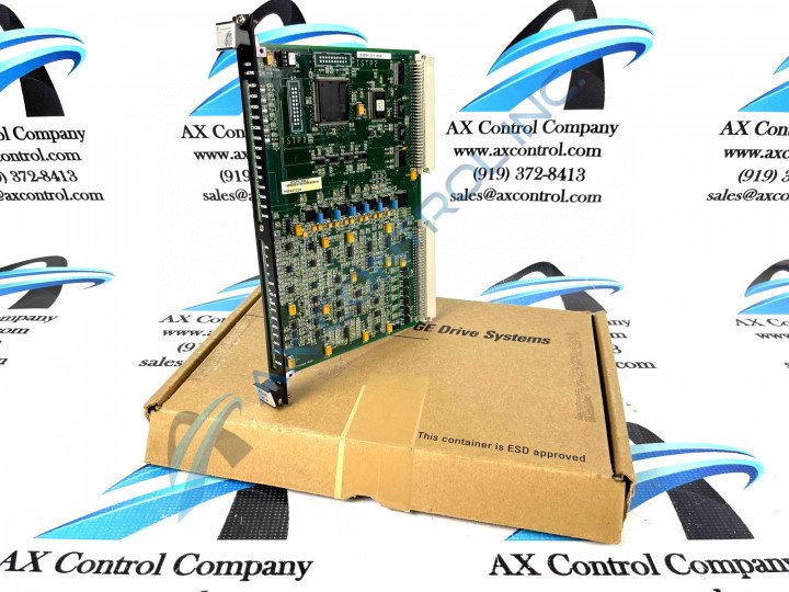
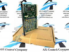
About the IS200FCGEH1ADA
The IS200FCGEH1ADA is a GE component created for the Mark VI system. The Mark VI turbine system is part of the Speedtronic series that has been used for gas and steam turbine management since the 1960s; this greatly increases its overall viability and desirability on its greater automated industrial marketplace. This IS200FCGEH1ADA device's Mark VI Series is additionally definable as quite the significant functional upgrade upon the previous industry-standard Mark V Turbine Control System Series of the same full extended series name, as the Mark V Series exists with a specific set of possible functional applications in gas and steam-based functional application settings alone, not including the Mark V Series' alternative energy-based wind turbine possible settings. This IS200FCGEH1ADA product's Mark VI Series is finally also well-desired given its status as one of the final-developed Speedtronic Mark product series from GE.
Hardware Tips and Specifications
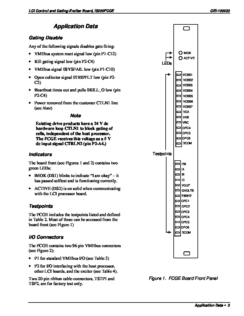
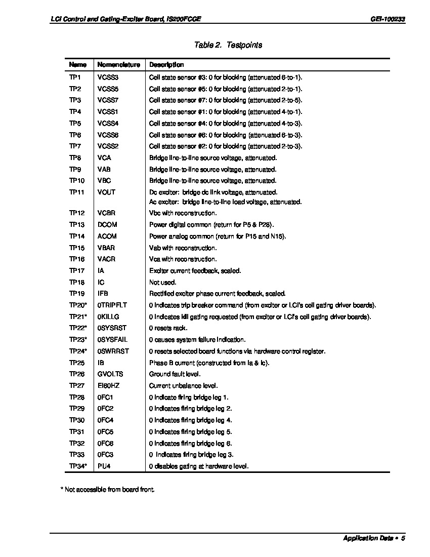
The Mark VI can be designed to manage large and small turbine setups by using either Simplex or Triple Redundant forms of the control system. Each circuit card in the control module is designed with diagnostics; diagnostics include software diagnostics and hardware diagnostics. The IS200FCGEH1ADA works within the Mark VI system as an LCI Control and Gating-Exciter card. This board has a front faceplate that includes two openings for access to 28 TP test points. The faceplate also has two LEDs. These LEDs are labeled “active” and “Imok.” The “Imok” LED blinks as an indicator that the board has passed a self-test and is functioning properly. The “Active” LED lights solidly when the board is communicating with the LCI processor board. Test points on the board are labeled “VCSS1 through VCSS7, VCA, VAB, VBC, OFC4 through OFC6, and DCOM, then IFB, IA, IB, IC, VOUT, GVOLTS, EI60Hz, OFC1 through OFC6, and DCOM.
The IS200FCGEH1ADA has several connectors. This includes a P1 VMEbus backplane and a P2 connector for Input/Output interfacing with other LCI boards, the host processor, and with the exciter. The board also has two 20-pin ribbon connectors that are for factory test use only. More information on the IS200FCGEH1ADA may be found in GE publication GEI-100233. This publication includes procedures and information on firmware, as well as installation instructions. According to these various relevant IS200FCGEH1ADA Board instructional manual materials made available above, this IS200FCGEH1ADA product 's gate firing processes are disabled when encountered by a series of specific signals. Each one of theses signals corresponds to a specific terminal pin, again as specified in the instructional manuals provided on this personalized product page. Some of these specific signals interrupting this central function of the IS200FCGEH1ADA Board include the:
- VMEbus system reset signal low signal
- Kill gating signal low signal
- VMEbus signal 0SYSFAIL low signal
- Open collector signal 0TRIPFLT low signal
- Heartbeat times out and pulls 0KILL_O low signal
- Power removed from the customer CTLN1 line signal


