About the IS200GDDDG1ABA
This IS200GDDDG1ABA printed circuit board product offering from General Electric was originally designed and manufactured specifically in the Mark VI Turbine Control System Series, as should have been revealed in our IS200GDDDG1ABA brief product description that was included above in brevity. This product series has to be identified as something of a functional step up from the previously-existing Mark V Turbine Control System Series of a similar full extended series name, as the Mark VI Series added on to the Mark V Series' established gas and steam turbine possible applications with the alternative energy-guided wind turbine possible functional application. The Mark VI Series is also valued on the greater general maturative industrial marketplace for its status as one of the last-developed GE Mark product series to incorporate the patented Speedtronic control system technology into a number of product offerings.
Hardware Tips and Specifications
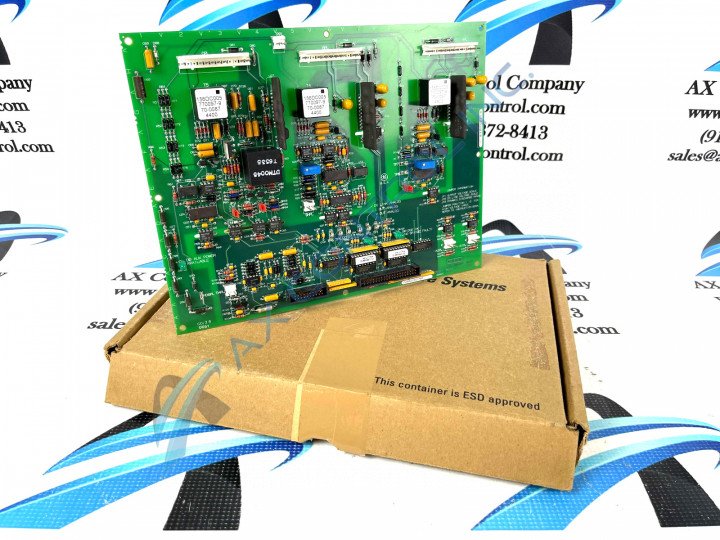
The IS200GDDDG1ABA is a PCB component for the Mark VI series from GE. Mark VI was the third generation of steam/gas turbine management systems from GE that ran with Triple Module Redundant architecture. This meant the system was built with three separate, complete power supplies, control modules, and IONets. This triple-redundant system helped improve the reliability of the system. The IS200GDDDG1ABA is a large PCB that is component-dense. It includes the following:
- Six resistor networks.
- Two trim potentiometers. These are marked “RV1” and “RV2.”
- Three jumper switches marked JP1 through JP3. The board is printed with information on these components. “JP1 output voltage scale. JP2 DC link voltage scale. JP3 dynamic discharge range. Jumper position 1 -2 for high voltage input. Refer to the instruction book.”
- Eight test points marked TP1 through TP8. TP1 is also marked V Out Analog. TP2 is also marked I Out Analog. TP3 is also marked DC Link Analog. TP4 is also marked DCOM.
- Two male PCB mating connectors. One of these is a twenty pin connector, the other a forty pin connector.
- Eight header connectors. Five are three position, two pin connectors. Three are twelve position, eight-pin connectors. Many of these are marked “W” and “R” on either side.
- One voltage regulator. This is an integrated circuit that provides a constant fixed output voltage regardless of the change in load or input voltage.
- Three green LEDs. These are marked DS100 “Bridge OK (No Bridge Fault,)” DS101 “IMOK,” and DS102 “DD AUX Power Available.”
- Eight transistors. Three of these components are marked as Q1 through Q3. Others are marked as diodes (D83) or integrated circuits(U6, U16).
- Three large components marked as diodes (D75/D50/D34) These are labeled with the information 156DC005 770097-9 70-0087 1200.
- Over thirty integrated circuits. Some integrated circuits are mounted vertically. Several are mounted to the board over long oval cut-outs in the board’s surface.
The IS200GDDDG1ABA is populated with ceramic, aluminum electrolytic and polyester vinyl capacitors. Resistors tend to be made of metal film. Please refer to manuals or data sheets from the original manufacturer for safety data and installation instructions.


