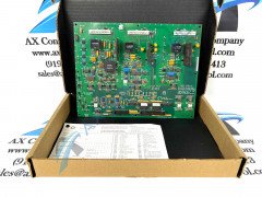
About the IS200GGXDG1A
The IS200GGXDG1A is a board component of the Mark VI system from General Electric. The Mark VI Series that this IS200GGXDG1A printed circuit board belongs to is really known as the Mark VI Turbine Control System Series in length, as it truly exists with specific functional applications in the control and management systems of General Electric-compatible gas, wind, and steam turbines, specifically. This does represent a significant functional upgrade upon the Mark V Turbine Control System Series of the same that originally preceded this IS200GGXDG1A device's Mark VI Turbine Control System Series, as the Mark V Serie's possible functional applications were restricted to gas and steam turbine assemblies alone. With this being the case, this IS200GGXDG1A printed circuit board product offering's Mark VI Turbine Control System Series is separately seen as a desirable GE Mark product series for its status as one of the final-developed GE Mark product series to incorporate the patented Speedtronic control system technology across a range of its differently-functioning PCB product offerings.
Hardware Tips and Specifications
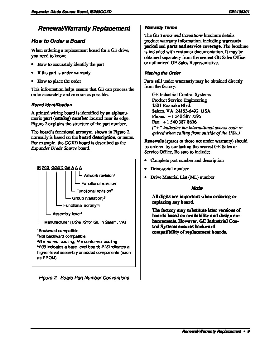
This board functions as an Expander Diode Source Board. The board provides fiber-optic and analog feedback hardware necessary for interfacing between the BICI board and a dynamic braking circuit. The IS200GGXDG1A is mounted within the control cabinet. Gating commands and status signals are interfaced using RS-422 transceivers. The IS200GGXDG1A uses power (high-frequency) from the GDPA board. The board’s seven stab-on connectors are used for grounding. This IS200GGXDG1A product is surrounded by at least some amount of originally-printed instructional manual materials online for the purposes of this IS200GGXDG1A personalized product page, which is somewhat atypical to the rest of Mark VI Series products available here. Three total types of signals are accepted in the special modular Mark VI Series assembly of this IS200GGXDG1A printed circuit board product offering. These are the source current transformers current feedback signals, the GDPA board power supply OK signal, which is octo-coupled, and finally the opto-coupled circuit continuity checking signal, which as delegated above, was included to indicate normative Voltage Feedback Attenuator or NATO Board plugging. This IS200GGXDG1A Expander Diode Source Board makes use of three total LED indicators, including the:
- DS1 ON for P5 OK signal LED
- DS2 ON for GDPA OK signal LED
- DS4 ON for 115V OK signal LED
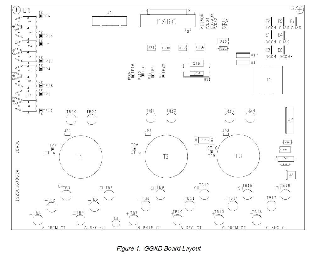
The IS200GGXDG1A has multiple components mounted on its surface. This includes 3 LED indicators, 6 3-terminal connectors, 15 test points, 3 2-terminal connectors, and a 4-pin connector. The board also has a J1 and J2 connector (20 pins and 6 pins respectively) for connections to the NATO and GDPA boards as well as a 50-pin connector that interfaces with the BICI. The IS200GGXDG1A uses berg and wire jumpers. Berg jumpers are used for burden resistor selection. Wire jumpers control selective grounding. In a typical operation configuration, E1 and E4 will be jumpered together, E2 and E5 will be jumpered together, and E3 and E6 will not be jumpered together. E7 always ties to chassis. More information about the IS200GGXDG1A, including information on application data, test points, adjustable hardware, I/O connectors, as well as important information regarding replacement procedures and handling precautions can be found within GE data sheets, user guides, and manuals. Please refer to these before beginning any replacement. AX Control is happy to provide you with a shipping quote upon request. We are happy to work with your courier service or one of several shipping companies.


