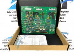
About the IS200GGXDG1ABB
The IS200GGXDG1ABB is an Expander Diode Source Board that was first made for the Mark VI system, as should have been mentioned above in our convenient manuals tab laden with original instructional manual materials. The Mark VI is part of the Speedtronic series that has provided gas/steam turbine management through different systems since the late 1960s. The MKVI is one of the last of these systems and includes a Windows-based PC operator interface and Ethernet communications. This IS200GGXDG1ABB device's greater Mark VI Turbine Control System Series' overall value on greater automated industrial promotional markets must be defined as inflated given its status as one of the final-developed GE Mark product series to incorporate the patented Speedtronic technology into many of its offerings. This IS200GGXDG1ABB device's Mark VI Series also must be considered quite the massive functional upgrade upon the existing Mark V Turbine Control System Series of a similar full extended series title, as the Mark V Series' established gas and steam-based functional environments added the alternative energy-focused wind turbine setting with the introduction of the Mark VI here.
Hardware Tips and Specifications
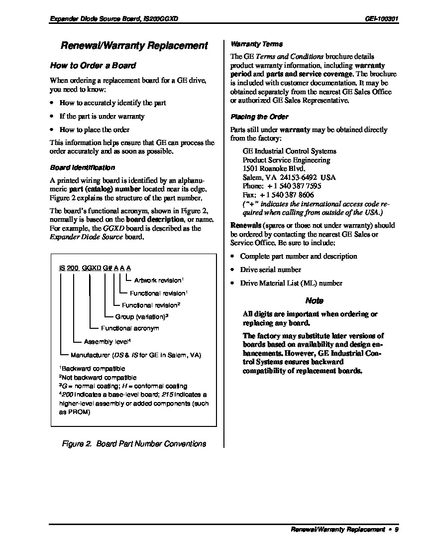
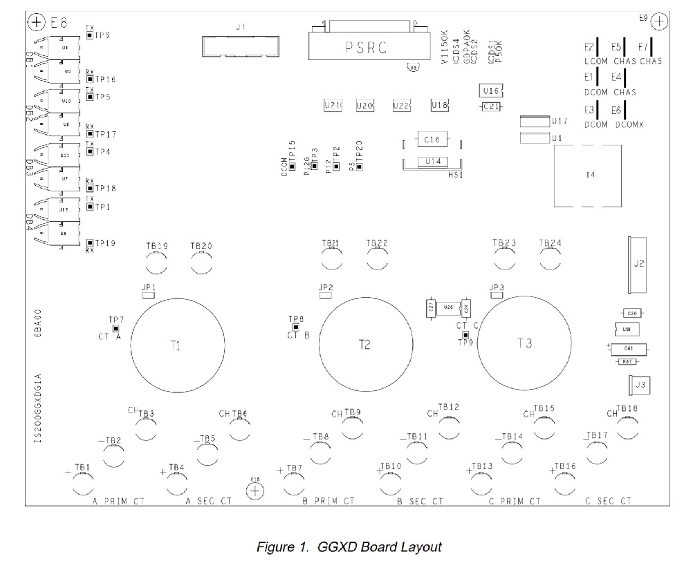
The IS200GGXDG1ABB provides analog and fiber-optic feedback hardware needed between the BICI (Bridge Interface Control Board) and a diode source or dynamic braking circuit. The IS200GGXDG1ABB is mounted in the control cabinet. Interfacing of gating commands between the IS200GGXDG1ABB and the BICI board occur via RS-422 transceivers. The IS200GGXDG1ABB receives high-frequency voltage inputs from the GDPA (Gate Driver Power Assembly) board. Seven stab-on connectors are used for grounding. The IS200GGXDG1ABB is built with three LED indicators, fifteen TP test points, six 3-terminal connectors and three 2-terminal connectors, and four pin connectors. These include a twenty-pin connector (J1) for connection to a NATO board, a six-pin connector (J2,) for connection to a GDPA board, a two-pin connector (J3) for 115 VAC control power, and a fifty-pin connector (PRSC) that functions as an I/O connector with the BICI board. Four duplex connectors (DB1 through DB4) are used for status feedback or firing commands of the DB IGCTs. More information on the board components and their uses may be found through GE publication GEI-100301.
Please review manufacturer publications referencing the IS200GGXDG1ABB for installation procedures. Manuals, user guides, and data sheets were provided by GE. Please follow all safety precautions and handling procedures recommended by the manufacturer. This I200GGXDG1ABB printed circuit board product offering from General Electric in specific is actually not the originally-developed product of its specific GE Mark product series functionality. In truth, that would have to be considered the IS200GGXDG1 parent Expander Diode/Source Board notably not utilizing this IS200GGXDG1ABB device's full three-fold significant revision history. According again to the IS200GGXDG1ABB datasheet provided above, this IS200GGXDG1ABB PCB is relatively customizable, offering both Berg and wire jumpers in its normal assembly. This IS200GGXDG1ABB device includes several LED indicators for functional fault condition diagnosis. Some of this IS200GGXDG1ABB device's LEDs include its:
- DS1 LED that activates for P5 OK signal
- DS2 LED that activates for GDPA OK signal
- DS4 LED that activates for 115V OK signal


