About the IS200GGXIG1AED
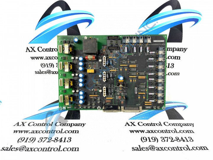
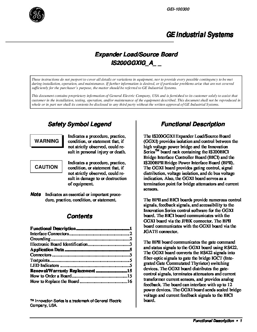
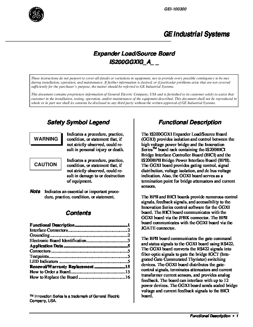
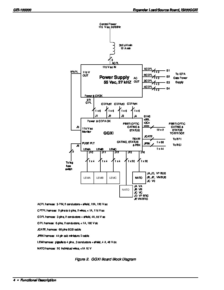
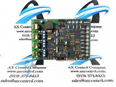
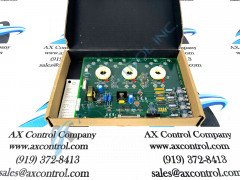
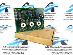
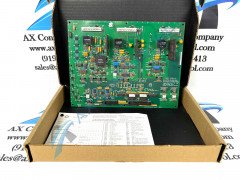
The IS200GGXIG1AED is designed as an Expander Load/Source Board. This means the board is a termination point for current sensors and bridge attenuators and also functions as an isolator for signals between the high-voltage bridge and the rack with the BICI and BPII boards. The IS200GGXIG1AED also provides voltage isolation and indication, gating control, and signal distribution. This IS200GGXIG1AED interfaces with power supplies via its J1-4 and J10-12 connectors. It interfaces with the 115V ac Monitor using its J5 connector. The J6 connector is for a Fuse fault monitor and J15/J16 are for voltage feedback. Two stab connectors provide grounding for the board. There are a total of nine stab-on connectors on the board’s surface. Other components include:
- nine LED indicators
- fourteen test points
- twelve fiber-optic connectors
- thirteen plug connectors
- transformers
- integrated circuits
- relays
IS200GGXIG1AED Connections Established
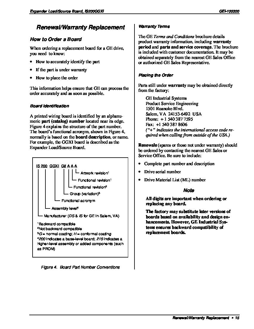
This IS200GGXIG1AED product's above-attached original instructional manual materials detail a set of important IS200GGXIG1AED qualities, which should have been stressed above. To begin, this IS200GGXIG1AED device's J1-starting power connectors establish a connection with the GDPA Board, which is important as it acts as this IS200GGXIG1AED device's power supply, as detailed above. The GDPA Board crucial to the normative functionality of this IS200GGXIG1AED Expander Load/Source Board is additionally available here at AX Control, with both repair and replacement options at your disposal. This IS200GGXIG1AED device's base printed circuit board features several individual hardware components that seek their own protection through differing applications of a thick normal style of PCB protective coating. Some of this IS200GGXIG1AED printed circuit board product offering's individual J1-starting power supply connectors include its:
- J1-1 GDPA1H or GDPA1OK signal connector
- J1-2 GDPA1R or GDPA1OK signal connector
- J1-3 NC or Not Connected connector
- J1-4 V48PA 48 V ac, or 27 kHz power from GDPA1 connector
- J1-5 NC or separate Not Connected connector
- J1-6 V48NA 48 V ac, or 27 kHz power from GDPA1 connector


