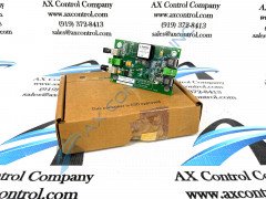
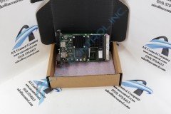
About the IS200ISBEH1A
The IS200ISBEH1A board component is part of the ISBus High-Speed Synchronous Communication system from General Electric. As one of the final industrial Speedtronic control systems released by GE, this part is considered compatible with the Mark VI series of Speedtronic drive components, which was designed as a complete control/protection/monitoring system that could meet the needs and requirements of industrial gas and steam turbines. This is considered a revised version of the preceding parent IS200ISBEH1A component; featuring a functional revision 1 rated at an "A" grade. The Mark VI Turbine Control System Series that this specific IS200ISBEH1A printed circuit board product belongs to is considered quite the desirable GE Mark product series on its greater market, likely given its status as one of the final-developed General Electric Mark product series to feature the patented Speedtronic control system technology across a swathe of its different offerings.
Hardware Tips and Specifications
This system is built with a PC-based HMI operator interface that uses a Microsoft Windows platform preloaded with GE’s proprietary CIMPLICITY software. The HMI can be reinitialized or replaced with no impact to processes running elsewhere on the system. The IS200ISBEH1A functions as an ISBus Extender board. It typically connects directly to the J11A interface on the CAPB Control Assembly Backplane board, where it is used to connect that board to higher-level controllers like an ACL_ board, although this IS200ISBEH1A board can also mate with the J12A interface on the same board. The IS200ISBEH1A is built upon DIN rails, and has six inputs/outputs located on opposite board edges. In terms of optical performance, the IS200ISBEH1A PCB is compatible with a range of I/O component options, including ST-type connected Hard Clad Silica (HCS) fiber or glass fiber connectors.
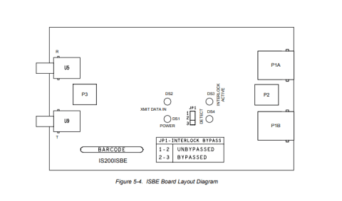
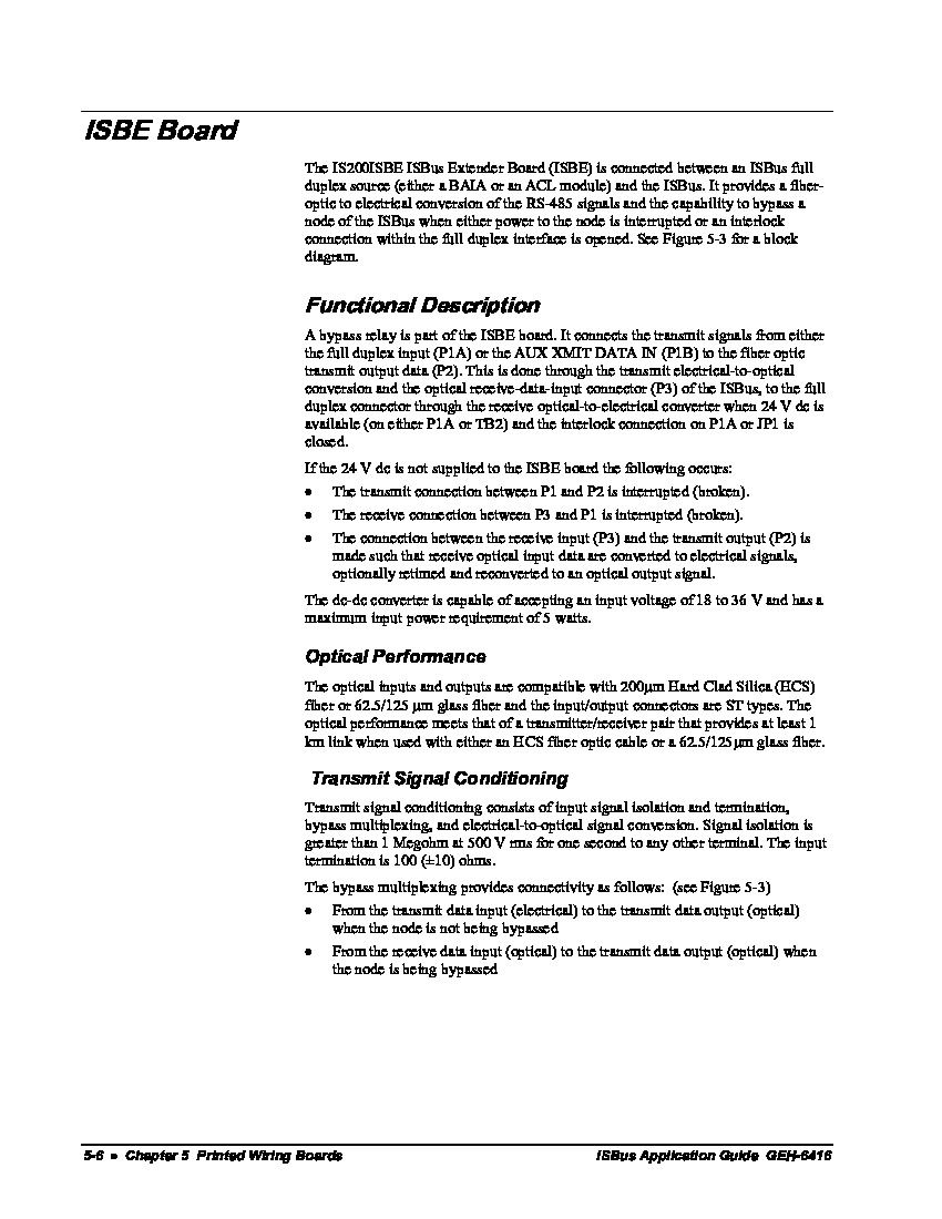
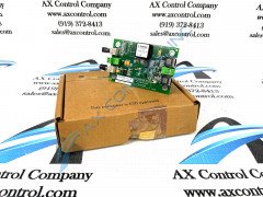
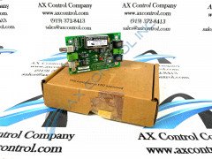
Each board edge on the IS200ISBEH1A includes a small terminal strip. One side has two plug connectors, while the other edge has two fiber-optic connectors. In between these edges, the board is populated by integrated circuits, LED indicators (red, yellow, and green), and a jumper switch to set bypass/unbypassed, capacitors, resistors, and diodes. The position of this customizable jumper switch is made apparent in GE's diagrammed IS200ISBEH1A printed circuit board layout embedded below. Most components on this PCB's base plate are marked or labeled, including this "ISBE" model's board ID as well as several other codes. All of the components present on the circuit board face of the IS200ISBEH1A are protected by a level of conformal-type PCB coating; designated by the letter "H" present in this product's unique part number. Conformal coating, while significantly lighter and thinner than its alternative in normal PCB coating, covers the entirety of the face of the circuit board it has been applied to; unlike with normal PCB coating. This Drive's series of LED indicators provide the drive administrator with valuable information concerning the normative functioning status of the greater drive assembly. The ISBus Communications series IS200ISBEH1A has a series of numerous LED lights, including:
- The "DS1" indicator that indicates a 24 V DC POWER current available to the drive component module that glows green when normative
- The "DS2" indicator that indicates a trasmit data input, labeled XMIT DATA IN. This drive component glows yellow when applicable.
- The "DS3" INTERLOCK ACTIVE LED indicator which identifies a lack of power to the bypass relay. This component LED glows green.
- The "DS$" DETECT indicator which glows green to indicate a correct optical date has been recieved.
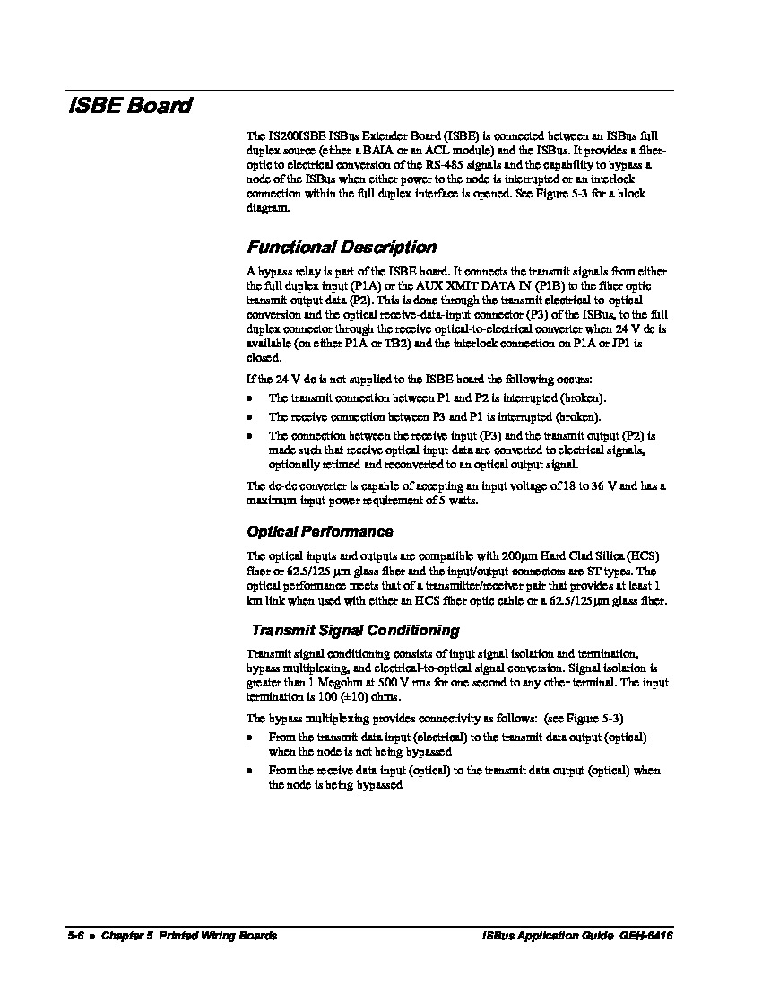
Additional information about proper installation techniques, maintenance, and handling can be found through original documentation like manual GEH-6416; attached for your convenience in the "manuals" tab above.
