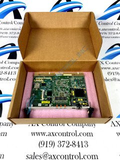
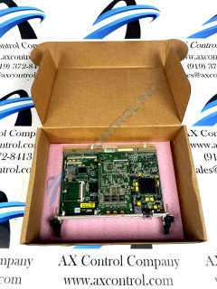
About the IS215UCCAM03A
This board, the IS215UCCAM03A board, is one of the UCCx controllers. The UCCx controller is based on a single-board computer known as the CompactPCI, or CPCI. This board is part of the Mark VIe system produced by General Electric, although this specific model is considered compatible with the later Mark VIeS system models as well. This model is essentially an IS215UCCAH3 board combined with an IS200EPMC, 128 MB of flash memory, and 128 MB of DRAM. The Mark VI Turbine Control System Series accommodating this IS215UCCAM03A CompactPCI assembly module device is something of a self-described GE Mark product series, given the fact that it exists with a series of possible functional applications in the control and management systems of General Electric-compatible gas, wind, and steam turbine automated drive assemblies. This must be considered quite the functional upgrade upon the previously-existing Mark V Turbine Control System Series of a similar full extended series name, as the Mark V Series' possible applications exist in more restricted gas and steam-based functional settings alone.
Hardware Tips and Specifications
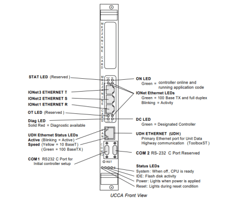
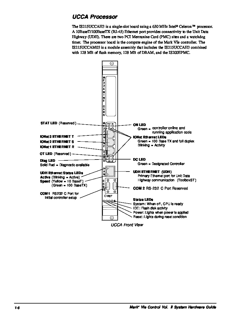
The IS215UCCAM03A CompactPCI is a single-slot processing board with a series of unique and important product specifications. This board has several LEDs on the front faceplate of the board. Some of these LEDs are; UDH Ethernet Status, Status, DC, Diag, IONet Ethernet, and ON LEDs. There are three statuses for the UDH Ethernet LED, there is an Active LED which will blink, and there is a Speed LED, which is green for the 100 BaseTX, and yellow for 10 Base T. These LED indicators are often triggered through an interruption of IS215UCCAM03A's environmental specifications or power requirements. For normative function, this UCCA PCB is advised to run in temperatures between 0 to 60 degrees Celsius, with an ideal storage temperature ranging from -45 to 85 degrees celsius. The humidity range for this model is outlined at 5 to 95%, and it carries an operating altitude of o to 10,000 feet with a storage altitude of 0 to 40,000 feet above sea level. In terms of voltage power inputs, the IS215UCCAM03A demands +3.3 V dc, 3.5 A typical, 4.25 A maximum and +5 V dc, 150 mA typical, 300 mA maximum rated voltages. There are a series of port and protocol specifications specfic to the IS215UCCAM03A board, which vary quite a bit. As displayed on the IS215UCCA components diagram below; the EPMC Ethernet Interface is made up of three ports, an RJ-45 connector, and a twisted pair of 10BaseT and 100BaseTX connectors. Within the EPMC Ethernet Interface, there are protocols that are used to communicate between the I/O packs and controllers; those protocols are TCP/IP protocols.
The oneport primary ethernet Interface handles a number of other protocol functions for this UCCA PCB module. One such TCP/IP protocol is deployed for communication between the UCCA board assembly's controller and toolbox, while another is defined as usable as effective alarm communication to various HMIs. Additional protocols handled through use of this interface include an EGD protocol for application-guided communication with CIMPLICITY® HMI, and acSeries 90-70 PLCs Ethernet Modbus® protocol designed to encourage third-party DCS and controller communications. The IS215UCCAM03A board will have at minimum one controller and up to four slots of CPCI rack with a maximum of two power supplies. Please note that if the first slot controller is removed then the remainder of the controllers will cease operation. If any of the boards require removal power must be removed from the rack. There are several ways that power from the rack can be removed, one of which is using a remote disconnect switch.
