About the IS200WEORG1A
The IS200WEORG1A printed circuit board was developed by General Electric shell company specifically for use alongside their Mark VIe series of turbine control products. The Mark VIe series control systems are relatively new; as their central focus is wind turbine control system applications. This particular Mark VIe series printed circuit board is relatively limited in terms of the amount of original factory-issued instructional material available online detailing it, but a swathe of supplementary information is still retrievable for the IS200WEORG1A through a diligent AX Control technician-led visual inspection, as well as through a careful breakdown of its functional IS200WEORG1A product part number. The IS200WEORG1A printed circuit board is a modified form of the original IS200WEORG1A parent board, featuring its sole functional revision graded at an "A" rating.
Hardware Tips and Specifications
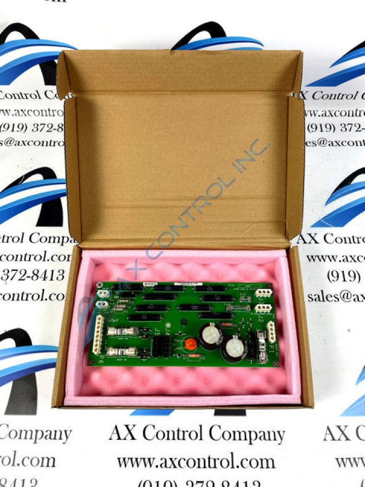
As stated earlier, the prospective IS200WEORG1A printed circuit board buyer does not have a complete amount of information at their disposal, at least in instructional materials available through the internet. A visual inspection, led by a trained AX Control technician is very informative, however. For starters, immediately noticeable on the base board of this WEOR-abbreviated PCB are two large, drum-style capacitors, labeled C1 and C3 respectively. The only other capacitor that exists the the IS200WEORG1A circuit board's greater assembly is the C2 capacitor, which is affixed to the base WEOR board in close proximity to the two drum-style C1 and C3 capacitors. This C2 capacitor is coated in a layer of bright orange specialized coating, and, like the two drum-style capacitors close by, features a series of factory-printed labels for component part visual identification. The three capacitors attached to the IS200WEORG1A board's base board are not the only voltage-supervisory components present in this model. A series of fifteen total resistors are present in the IS200WEORG1A; mostly relatively large, black-colored resistors that contain their own set of factory labels. Resistors 1, 2, 3, 8, 5, and 9 on the WEOR board are all different styles of resistor from their MEXICO-labeled counterparts, although all of these remaining resistors are quite a bit smaller in component size. Five total fuses are visible on the IS200WEORG1A PCB, each of which labeled with proper voltage specifications, including 250V fuses and 3 600V fuses. Five insulated factory-drilled holes are available on this WEOR board's base board, included for installation purposes; with one of these drilled holes existing in about the exact center of the printed circuit board. Beyond those mentioned above, a number of relevant component labeled are included for the drive assembly administrator's convenience, including but not limited to:
- the FA/02 LI/00 label
- the J4 and J5 jumper labels, part of a greater jumper labels inclusion
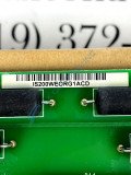
- an instance of the IS200WEORG1A part number
- the crimp clearance label for the R1, R2, R3, R5, and R9 resistors
- the FROM 230L-N SOURCE 250VA MAX label
- the PJ2J0A9 barcode label
- a printed General Electric logo label
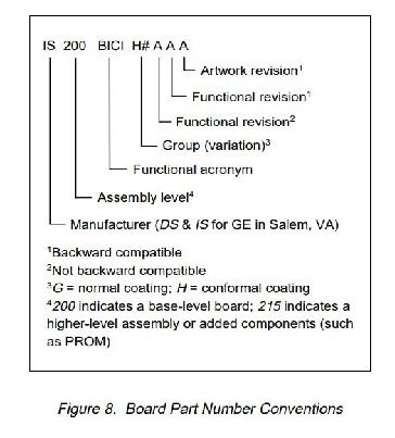
All of these specified component parts should be symbolized by the WEOR functional acronym that is included in the IS200WEORG1A individualized product part number. This part number can reveal a slew of important information to the prospective IS200WEORG1A Mark VIe series board purchaser, including its original manufacturer location, its industry-respected functional acronym, its Mark VIe series grouping, its PCB coating style, and its revision history. For a fully-diagrammed explanation of the functional IS200WEORG1A part number, please make use of the IS200WEORG1A Part Number Breakdown embedded above in the "manuals" tab.


