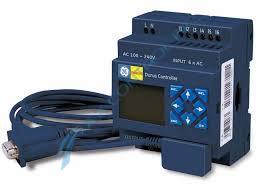
12 Point Power Source With 4 Transistor Outputs, 2 Analog Inputs | Image
3 year warranty

12 Point Power Source With 4 Transistor Outputs, 2 Analog Inputs | Image
12 Point Power Source With 4 Transistor Outputs, 2 Analog Inputs - Wiring Diagram Image

IC210DDD012

    Varying star amount pictures Varying star amount pictures Varying star amount pictures Varying star amount pictures Varying star amount pictures
  • 5.00 (4)
  • Click a star to rate this product
    Varying star amount pictures Varying star amount pictures Varying star amount pictures Varying star amount pictures Varying star amount pictures
  • 5.00 (4)
  • Click a star to rate this product
12 Point Power Source With 4 Transistor Outputs, 2 Analog Inputs

AVAILABILITY:

CALL FOR AVAILABILITY

Sell Surplus: Have a IC210DDD012 to sell? Sell Now
Exchange Credit: Learn more about our exchange credit program
  • Part Number: IC210DDD012
  • SKU: IC210DDD012GFP
  • Manufacturer: GE Fanuc PLC
  • Series: Durus Controllers

Product Description

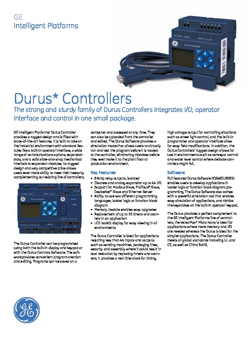
IC210DDD012 is a Durus-12 controller that is manufactured by GE Fanuc Automation. This controller has a DC 12 point power source, and it is expandable. This part is offered with or without an LCD screen and keypad. Motion requires a 1KHz input and PWM output. The specifications are (6) 24VDC input and (4) transistor output. There are 2 analog inputs.

Field wiring in the case of IC210DDD012 requires use of a 3.5mm2 cable as the external wire. Do not route I/O signal wires parallel to power wires or high current wires. Do not place I/O signal wires in the high-current cable trays. To ensure good contact, make sure to firmly fasten the wires with lock screws. Use 4 ~ 6kgf.cm torque to tighten the lock screws. Only connect sensors via a 3-wire cable. Protective fusing for outputs is not included in Durus modules, so external fusing should be installed between each power source and load. The Durus manual offers solutions for sensor wiring, field wiring, relay output wiring, and transistor output wiring.

The power supply and the I/O supply must have the same power source. Add termination to the first and last device on a multidrop link, and only short circuit the first and last module. Transfering application programs is simple because there is a specified port for this purpose on all Durus controllers. In order to install a memory option module, remove the cover for the memory compartment on the controller and plug the memory option module into the slot.

  • IC210DDD012-AA
  • IC210DDD012-BA
  • IC210DDD012-BB
  • IC210DDD012-CB
  • IC210DDD012-CD
  • IC210DDD012-DC
  • IC210DDD012-FG
  • IC210DDD012A
  • IC210DDD012B

Repair Services For IC210DDD012

Type Lead Time Price Action
Repair Service 1-2 weeks $327

Our highly skilled technicians can repair your IC210DDD012. All of our repairs come with a 3 Year AX Control Warranty. Please contact us for additional information about our repair process. To receive the repair pricing and lead time listed above please process your repair order via our website. The following repair options may be available upon request:

  • 48-72hr Rush Repair
  • Detailed Repair Reports
  • AX Control Certificate of Warranty

AX Control Warranty Info

All products we sell are backed by our unparalleled warranty. A warranty certificate will be provided with your order upon request.
All PLCs, HMIs, and Turbine Control Boards: 3 Years
All AC/DC and Servo Drives: 2 Years
All Motors: 1 Year
Learn More

IC210DDD012 Manuals, White Papers, Data Sheets, and Troubleshooting