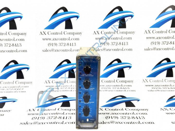
About the 139-V-TC-FLC
During the operation of this relay, there is only one phase current for each of the three attached motor phases. Each of the currents is required for inputting a current into the 139-V-TC-FLC relay proportional to the phase current associated with the attached motor. The polarity of the motor is not relative to the relay but it is highly recommended that the polarity is observed to ensure that it remains within the standard.
Several indicators and controls make up the front of the 139-V-TC-FLC relay. Some examples of the controls and indicators used with this device are start time, a reset push button, maximum load control, and others. Each of the indicators has its own function. For example, the reset push button on this model is used to reset the relay after a trip has occurred in case the memory lockout condition on the relay does not function properly.
More information regarding the installation, relay testing, setup/use, and theory of operation of this relay can be found in the 139 Series Relay Protection Instruction Guide.


