169PLUS-100N-125VDC

    Varying star amount pictures Varying star amount pictures Varying star amount pictures Varying star amount pictures Varying star amount pictures
  • 5.00 (2)
  • Click a star to rate this product
    Varying star amount pictures Varying star amount pictures Varying star amount pictures Varying star amount pictures Varying star amount pictures
  • 5.00 (2)
  • Click a star to rate this product
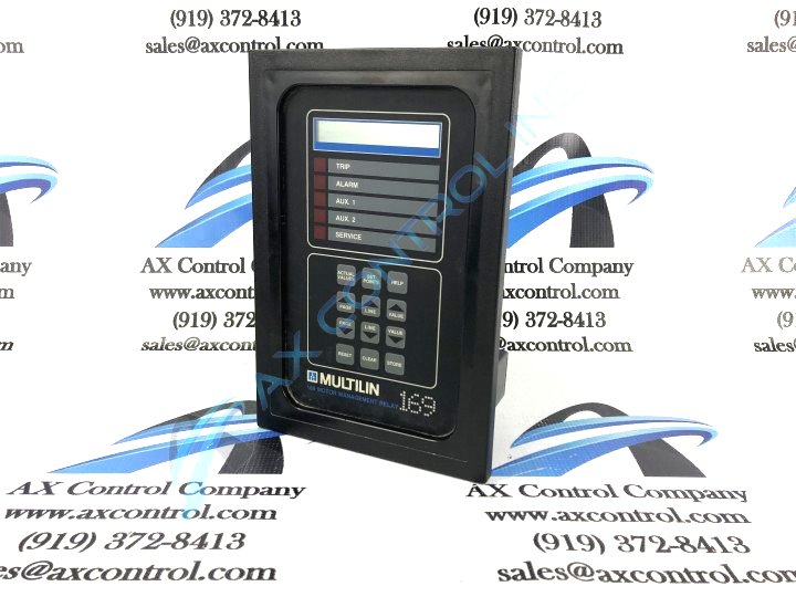
Boasting a number of features over the non-PLUS base model, GE Multilin's 169PLUS-100N-125VDC is perfect for motor management, monitoring, and protection.

AVAILABILITY:

CALL FOR AVAILABILITY

Sell Surplus: Have a 169PLUS-100N-125VDC to sell? Sell Now
Exchange Credit: Learn more about our exchange credit program
  • Part Number: 169PLUS-100N-125VDC
  • SKU: 169PLUS100N125VDCGM
  • Manufacturer: GE Multilin
  • Series: 169 Motor Management Relay

169PLUS-100N-125VDC Technical Specifications

Manufacturer General Electric Multilin (GE)
Manufacturing Location Markham, Ontario, Canada
Model Number 169PLUS-100N-125VDC
Phase Current Input Range 0.05 to 12 × phase CT primary amps setpoint
Relay Contacts Maximum Operating Current 10 Amps
RTD Input Display Accuracy ±2° C
RTD Trip/Alarm Setpoint Range 0 to 200°C
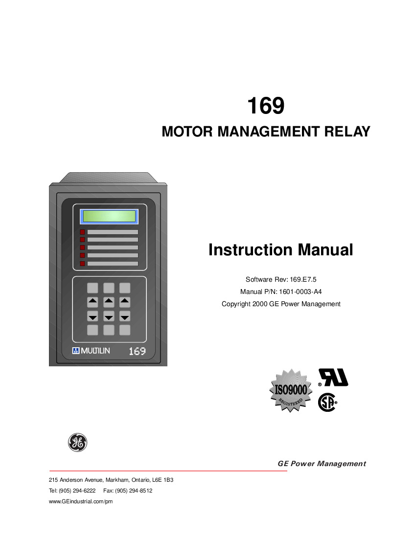
Manual 1601-0003-A4
Operating Temperature Range 14°F to 140°F
Overload Curve Detection Level ±1% of primary CT amps

About the 169PLUS-100N-125VDC

Boasting a number of features over the non-PLUS base model, GE Multilin’s 169PLUS-100N-125VDC is perfect for motor management, monitoring, and protection. The ‘PLUS’ version of the relay is able to learn additional motor parameters over the base version such as acceleration time, negative sequence current K factor, cooldown rates, motor inrush current, and cooldown rates. That learning is then applied by the device to improve the relay’s protective abilities in an ongoing fashion.

In addition to the aforementioned learning capabilities, the 169PLUS-100N-125VDC also includes the following features that the base model does not include:

  • Auxiliary Relay Contacts: These two contacts can be used to trip devices other than the motor starter, such as the main circuit breaker. This provides greater flexibility for the motor system.

  • RS422 Communications Port: This port allows the relay to connect to computers,  programmable controllers, and other relays. 

  • Spare Input Terminals: Added terminals 44 and 45 allow additional relay contact inputs. They can be set for trip or alarm functions and help further protect the system. A twisted pair of wires should be used with these terminals.

Out of case, the relay has an approximate height of 5 inches, an approximate length of 11 inches, and an approximate width of 7.5 inches. It should be mounted away from strong magnetic fields and high current conductors. Due to the useful status LEDs at the front of the relay, the unit should be mounted so that users can view it easily in order to reference system health and become aware of changes within the motor.

Frequently Asked Questions about 169PLUS-100N-125VDC

What is the 169PLUS-100N-125VDC?

The 169PLUS-100N-125VDC is an enhanced model of General Electric Multilin's 169 series that protects, manages, and monitors three phase motor systems. It is a modern, microprocessor-based unit that offers a wide array of protection, monitoring, and diagnostic elements in a single, compact device. 
What are the control power features of the 169PLUS-100N-125VDC GE Multilin motor management relay?
The 169PLUS-100N-125VDC is a motor management GE Multilin relay of the 169 series. As indicated by the 125VDC found in the part number, this 169 Plus motor management relay has a 125 volt DC control voltage. The other potential options at this order specification are 120 AC, 240 AC, 24 DC, 48 DC, or 250 DC.
What are the physical dimensions of the 169PLUS-100N-125VDC motor management GE Multilin relay?
The 169PLUS-100N-125VDC is a member of the GE Multilin 169 Plus family of motor management relays. These relays are fabricated with a metal and plastic housing with a front panel that includes the keypad, display, and various light indicators. As indicated in the user manual in Figure 2-1, the front panel dimension is 7.570 inches (192 mm) by 11.375 inches (289 mm). The indicators on the front include trip, alarm, aux 1, aux 2, and service indicators.  When viewing a 169 Plus motor management relay from the side view, the depth of the unit from the front panel is 4.77 inches. The mounting surface however is located inset from the face by 0.5 inches. In order to mount the unit, the relay is equipped with four .218 inch diameter mounting holes on the rear as viewed from the rear of the unit.  Additional phase and ground fault CTs can be provided if necessary; however the dimensions of the unit change slightly with the inclusion of these CTs, but may be found in Figure 2-2 of the manual.

Reviews For 169PLUS-100N-125VDC

Internal Review
(5.0)

The 169PLUS-100N-125VDC also includes custom curve selectability; if the standard overload curves are not best suited to the system, users can enter their own breakpoints and form a custom curve that will better serve their motor. The 169 PLUS's custom curve is useful in particular environments where motor stator and rotor thermal capacities are significantly different than the standard, such as in regard to induced fan drives. -AX Control Tech Team

Repair Services For 169PLUS-100N-125VDC

Type Lead Time Price Action
Repair Service 1-2 weeks $1250

Our highly skilled technicians can repair your 169PLUS-100N-125VDC. All of our repairs come with a 3 Year AX Control Warranty. Please contact us for additional information about our repair process. To receive the repair pricing and lead time listed above please process your repair order via our website. The following repair options may be available upon request:

  • 48-72hr Rush Repair
  • Detailed Repair Reports
  • AX Control Certificate of Warranty

AX Control Warranty Info

All products we sell are backed by our unparalleled warranty. A warranty certificate will be provided with your order upon request.
All PLCs, HMIs, and Turbine Control Boards: 3 Years
All AC/DC and Servo Drives: 2 Years
All Motors: 1 Year
Learn More