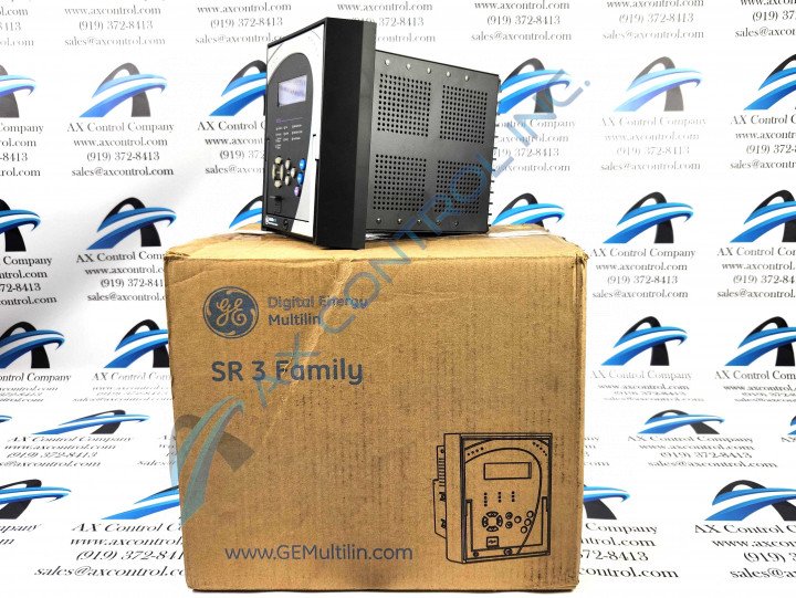
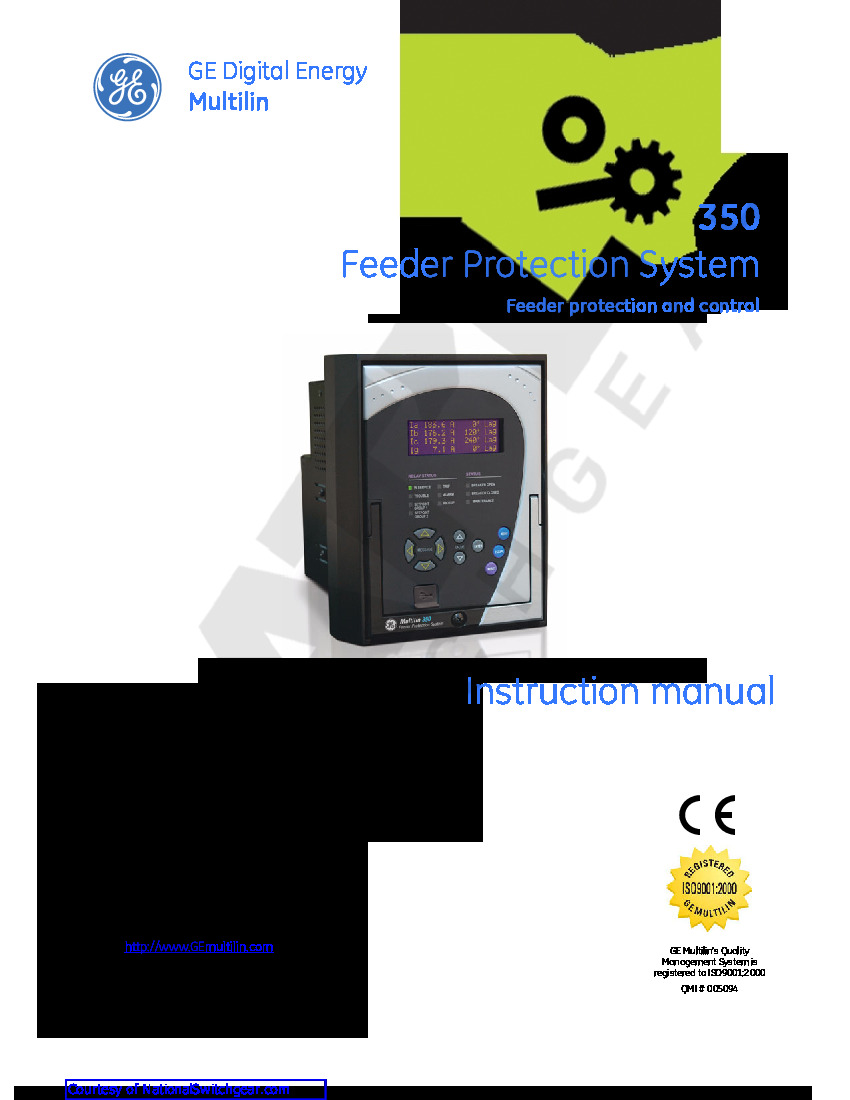
About the 350-E-P5-G5-L-E-S-N-N-SN-D-N
When the 350-E-P5-G5-L-E-S-N-N-SN-D-N relay was being designed it was being designed with over-current protection in mind for low voltage and medium voltage distribution feeders. This model was designed for protection for both small and medium-sized generators, transformers, distribution bus bars, and motors.
Several LEDs occupy the front panel of the 350-E-P5-G5-L-E-S-N-N-SN-D-N relay, which include but are not limited to the In-Service, Trip, Breaker Closed, Maintenance, and Alarm LEDs. Each of the LEDs all have different color indications which can be found in either of the GE Multilin 350 Feeder Protection System Guides. Another feature of this relay are the range of setpoints which include the pickup, delay, function, and relay setpoints. Thirty-two virtual inputs also make up this relay, the relays can be individually programmed to acknowledge the input commands entered through the keypad or by using the standard communication protocols.
There are two FlexCurve setpoints available on the 350-E-P5-G5-L-E-S-N-N-SN-D-N relay. Both of these setpoints are user-configurable and are typically labeled A or B. All of the programming needed for the two setpoints can be done through the EnerVista SR3 Setup software. An example of what FlexCurve A will look like can be found in a diagram on page fifty-eight of chapter six.
While both of the attached manuals are useful in finding out information about this relay through the order codes the GEK-113507T instruction guide is much more extensive than the GEK-113509C guide. It is also important to note that the latter of these two manuals is considered outdated due to the lack of information regarding the relay itself and also the lack of order code information.


