565-5-5-A

    Varying star amount pictures Varying star amount pictures Varying star amount pictures Varying star amount pictures Varying star amount pictures
  • 4.33 (3)
  • Click a star to rate this product
    Varying star amount pictures Varying star amount pictures Varying star amount pictures Varying star amount pictures Varying star amount pictures
  • 4.33 (3)
  • Click a star to rate this product
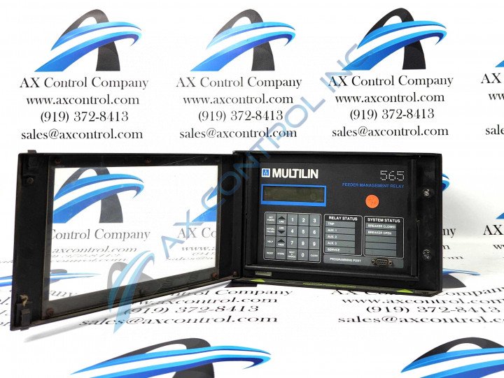
The 565-5-5-A relay is one of the basic Digital Feeder Management Relays. The power supply voltage this model operates on is 90-260 VAC or 95-280 VDC. The ground CT rating for this model is also 5 Amps.

AVAILABILITY:

CALL FOR AVAILABILITY

Sell Surplus: Have a 565-5-5-A to sell? Sell Now
Exchange Credit: Learn more about our exchange credit program
  • Part Number: 565-5-5-A
  • SKU: 56555AGM
  • Manufacturer: GE Multilin
  • Series: 565/575 Feeder Management Relay

565-5-5-A Technical Specifications

Manufacturer General Electric Multilin (GE)
Manufacturing Location Markham, Ontario, Canada
Model Number 565-5-5-A
Number of Relay Status Indicators 5
Number of Setpoint Groups 11
Power Factor Alarm Descroption Disabled/Enabled
System Status Indicators Breaker Open and Closed
Display Type 32-Character
Analog Output Factory Setpoint 4-20 mA
Display Modes Quantity Three; Help, Setpoints, and Actual Values Mode

About the 565-5-5-A

Part of the 565 series, the 565-5-5-A is a digital feeder management relay produced by General Electric Multilin. This relay has a phase CT rating of 5 amps and a ground CT rating of 5 amps. The control volts are 90-260 V AC and 95-280 V DC. Protective features include ground current protection and time/overcurrent phase protection. Relay testing on this unit involves the power loss check, the analog output function check, the overvoltage trip and alarm check, the analog input function check, the undervoltage trip and alarm check, the output relay functional check, the voltage input function check, the ground curve verification, the ground instantaneous pickup and trip check, the ground current input function check, the phase overcurrent curve verification, the phase current input function check, and more.

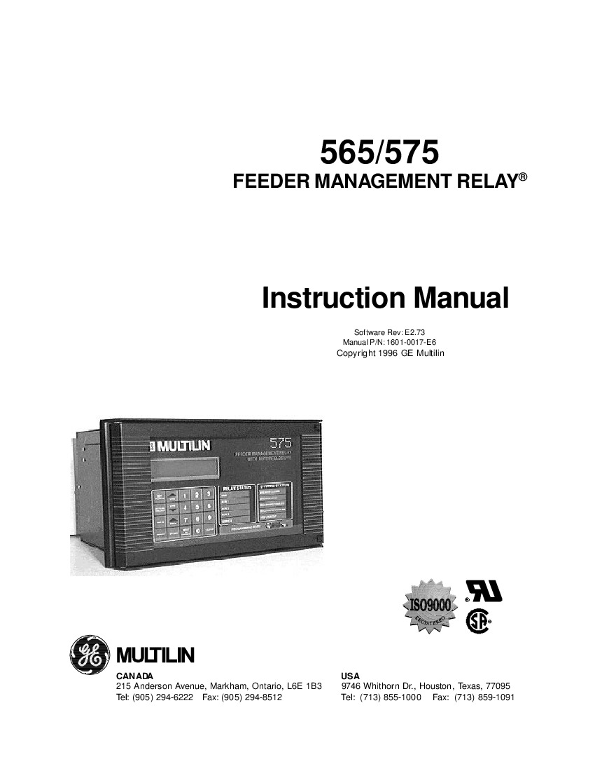
Troubleshooting is simple on the digital feeder management relay; simply follow the instructions that are listed in the user instruction manual in the troubleshooting section beginning on page B-1. If the display does not light up, ensure that the relay is fully inserted into the drawout case, and check the control power voltage and the control power fuses. For reference, refer to the relay wiring diagram in the user instruction manual. If a message does not appear when the display lights up, check that the control voltage is within the correct limits. If the incorrect phase current readings are displayed, use a clamp-on ammeter to measure the current flowing into the 565 CT terminals. The correct phase CT primary rating must be entered by the user into setpoints for the correct phase current readings to be displayed.

Frequently Asked Questions about 565-5-5-A

What is the 565-5-5-A? 

The 565-5-5-A is a Feeder Management Relay that integrates an array of control, protection, and management features in a single, compact unit. The relay is designed to provide accurate and holistic feeder protection regardless of operating conditions. 

How does the setpoint system function for the Feeder Management Relay?

System settings ('setpoints') allow for highly versatile relay logic that lays down guidelines for various system processes and responses. For example, users can set thresholds and time intervals for alarm and trip functions, i.e. assigning an alarm to be triggered when system temperatures reach an assigned value for an assigned amount of time. Settings can be edited locally through the keypad and LCD or through Multilin's EnerVista software program. Setpoints are tramper-proof, which is accomplished by use of an access wire jumper and system passcodes.

Reviews For 565-5-5-A

Internal Review
(4.0)

Due to the simplistic order code for this device, it is evident that this relay is a base model, as a base model there is no optional card that can be used for breaker discrepancies and other functions. Order a different relay if a breaker discrepancy, printer driver, or other features are needed. - AX Control Technician

Repair Services For 565-5-5-A

Type Lead Time Price Action
Repair Service 1-2 weeks $1686

Our highly skilled technicians can repair your 565-5-5-A. All of our repairs come with a 3 Year AX Control Warranty. Please contact us for additional information about our repair process. To receive the repair pricing and lead time listed above please process your repair order via our website. The following repair options may be available upon request:

  • 48-72hr Rush Repair
  • Detailed Repair Reports
  • AX Control Certificate of Warranty

AX Control Warranty Info

All products we sell are backed by our unparalleled warranty. A warranty certificate will be provided with your order upon request.
All PLCs, HMIs, and Turbine Control Boards: 3 Years
All AC/DC and Servo Drives: 2 Years
All Motors: 1 Year
Learn More