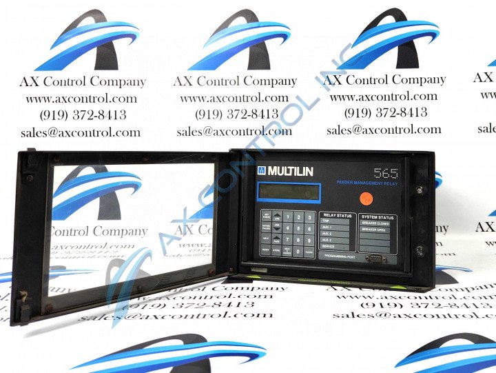
565-5-5-O-A-E

    Varying star amount pictures Varying star amount pictures Varying star amount pictures Varying star amount pictures Varying star amount pictures
  • 4.50 (2)
  • Click a star to rate this product
    Varying star amount pictures Varying star amount pictures Varying star amount pictures Varying star amount pictures Varying star amount pictures
  • 4.50 (2)
  • Click a star to rate this product
Feeder Management Relay 565-5-5-O-A-E is an extended option that operates on 90-260 VAC & 95-280 VDC and comes with an additional optional card. There are two current types available for this model both of which run on a rating of five amperes.

AVAILABILITY:

IN STOCK
SHIPS IN 3-5 DAYS

Sell Surplus: Have a 565-5-5-O-A-E to sell? Sell Now
Exchange Credit: Learn more about our exchange credit program
  • Part Number: 565-5-5-O-A-E
  • SKU: 56555OAEGM
  • Manufacturer: GE Multilin
  • Series: 565/575 Feeder Management Relay

565-5-5-O-A-E Technical Specifications

Manufacturer General Electric Multilin (GE)
Manufacturing Location Markham, Ontario, Canada
Model Number 565-5-5-O-A-E
Ground Overcurrent Protection Instantaneous Overcurrent Pickup Range 1 to 7 Times Ground Pickup in Steps of 0.5
Isolated Analog Output Range Software Selectable 0-1 mA or 4-20 mA
Operating Temperature Range -30 to 80 °C
Voltage Inputs 48 to 240
Display Accuracy for Load Currents ± 3% from 25-100% CT primary
Display Update Rate Greater than Once Per 2 Seconds
Frequency Measurement Accuracy ± 0.1 Hz

About the 565-5-5-O-A-E

Relay model 565-5-5-O-A-E is one of the Digital Feeder Management units produced by General Electric Multilin and is primarily used for protecting three-phase feeders. Not only does it protect the feeders and associated equipment, but it can also help prevent any type of personal injury. Continuous and reliable power will be sent to the distribution network to ensure that the feeder protection relay is protecting personnel using the model as well as the network it is being used on. The minimum requirements for the relay are ground current and voltage network monitoring and phase current monitoring which will provide indications of potential faults. 

The system status of the 565-5-5-O-A-E relay will be displayed at all times by the LED indicators. If more information is required or wanted the display screen will have full information is requested from the keypad on the device. The screen on this relay can display what has caused a potential alarm or trip. 

There are terminals located on the back of the 565-5-5-O-A-E device. Terminals one through eight of this model can accept external switch inputs. These switches are also considered user-configurable and can be set to whatever setting the user requires. The terminals will also prevent certain types of feeder breaker trips and can also introduce a time-delayed alarm if required as well. 

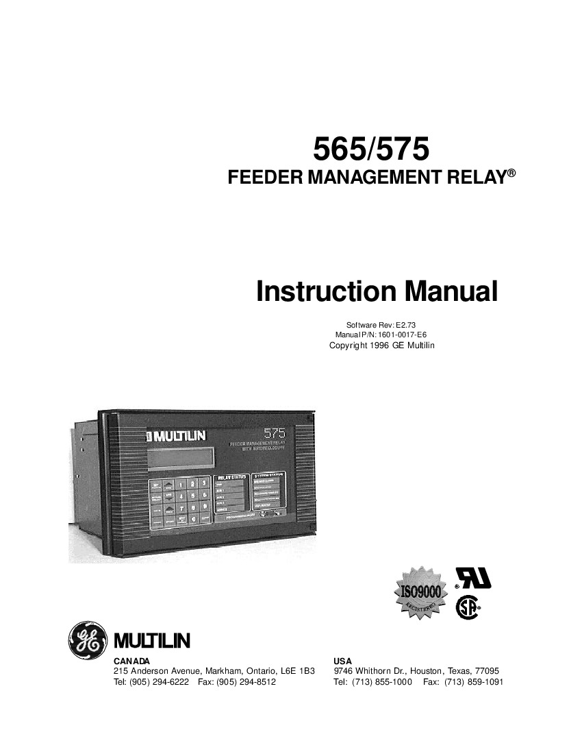
All of the above information can be found in the GE 1601-0017 E2.73 565/575 Feeder Management Relay Instruction Manual which has information regarding the Display and Keyboard, Actual Values Mode, Relay Testing, and more. 

Frequently Asked Questions about 565-5-5-O-A-E

What is the 565-5-5-O-A-E?

The 565-5-5-O-A-E is a Feeder Management System that protects, controls, and monitors three-phase feeder systems. The system can monitor phase current, voltage, and ground current and provide appropriate responses in the event that fault conditions occur. 

What are the memory features of the relay?

The 565-5-5-O-A-E includes an event logging feature that provides a record of the events that lead up to system faults. These events are listed in order and accurately time-stamped, reducing the amount of time required for troubleshooting prior to maintenance. The logs also include the cause of the trips for the sake of identifying major recurring issues.

Reviews For 565-5-5-O-A-E

Internal Review
(4.0)

Occasionally malfunctions will occur on this relay, one of which is that the no display for analog in signal in actual values mode is likely not to show up, if this occurs, please verify that the analog input feature has been enabled and also check that analog input signals are appearing at terminals 23 and 24. If this does not fix the issue refer to the setpoints on page five of the manual. - AX Control Tech Team

Repair Services For 565-5-5-O-A-E

Type Lead Time Price Action
Repair Service 1-2 weeks $1545

Our highly skilled technicians can repair your 565-5-5-O-A-E. All of our repairs come with a 3 Year AX Control Warranty. Please contact us for additional information about our repair process. To receive the repair pricing and lead time listed above please process your repair order via our website. The following repair options may be available upon request:

  • 48-72hr Rush Repair
  • Detailed Repair Reports
  • AX Control Certificate of Warranty

AX Control Warranty Info

All products we sell are backed by our unparalleled warranty. A warranty certificate will be provided with your order upon request.
All PLCs, HMIs, and Turbine Control Boards: 3 Years
All AC/DC and Servo Drives: 2 Years
All Motors: 1 Year
Learn More