750-P5-G5-S1-HI-A20-R

    Varying star amount pictures Varying star amount pictures Varying star amount pictures Varying star amount pictures Varying star amount pictures
  • 5.00 (2)
  • Click a star to rate this product
    Varying star amount pictures Varying star amount pictures Varying star amount pictures Varying star amount pictures Varying star amount pictures
  • 5.00 (2)
  • Click a star to rate this product
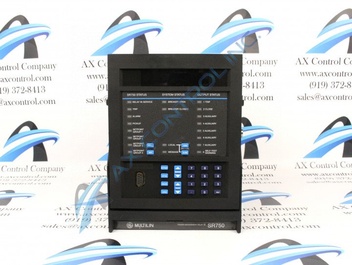
Able to be mounted on a standard 19-inch panel alone or alongside other 750 units, the 750-P5-G5-S1-HI-A20-R Feeder Management Relay is an excellent choice for distribution feeder control and protection needs. Features such as time overcurrent protection and frequency protection extend distribution feeder life by shielding system components in the event that issues arise within the system.

AVAILABILITY:

IN STOCK
SHIPS IN 3-5 DAYS

Sell Surplus: Have a 750-P5-G5-S1-HI-A20-R to sell? Sell Now
Exchange Credit: Learn more about our exchange credit program
  • Part Number: 750-P5-G5-S1-HI-A20-R
  • SKU: 750P5G5S1HIA20RGM
  • Manufacturer: GE Multilin
  • Series: 750/760 Feeder Management Relay

750-P5-G5-S1-HI-A20-R Technical Specifications

Analog Outputs Type Active
Communications Protocol Modbus RTU or DNP 3.0
Features Red Breaker Closed LED
Frequency 25 to 60 Hz nominal
Insulation Voltage 300 V
Overvoltage Pickup Level 0 to 1.25 × VT in steps of 0.01
Waveform Capture Channels 4 currents, 3 voltages, 14 logic input states and 8 output relays

About the 750-P5-G5-S1-HI-A20-R

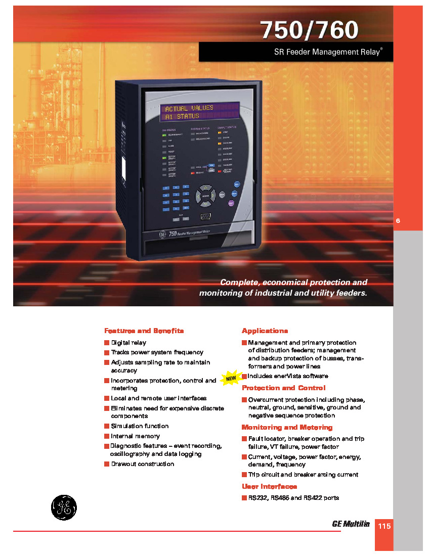
Able to be mounted on a standard 19-inch panel alone or alongside other 750 units, the 750-P5-G5-S1-HI-A20-R Feeder Management Relay is an excellent choice for distribution feeder control and protection needs. Features such as time overcurrent protection and frequency protection extend distribution feeder life by shielding system components in the event that issues arise within the system. Other features like oscillography or data logging diverge from being primarily protective and instead offer insights into system efficiency and where issues begin. Users can view, trend, graph, and export this data for further analysis and subsequently make efforts to improve the system.

The 750-P5-G5-S1-HI-A20-R features multiple communications ports, including the RS232 port on the front of the relay and the RS422/RS485 ports on the back of the case. The RS232 port is most suitable for direct connection to a computer running GE Multilin’s EnerVista 750 software, while the RS422/RS485 ports are more optimal for users seeking to monitor multiple relays at one time. The EnerVista 750’s Plug & Play feature makes configuring the software program straightforward and quick. Within the program, users can create, remove, and edit system settings to adjust how processes unfold within the relay. Additionally, users can view system data collected through metering, data logging, and waveform capture functions. This data can be plotted using features inherent to the EnerVista 750 software program.

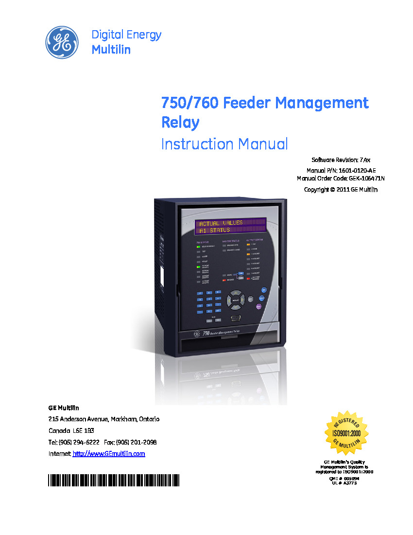
These aforementioned user-configurable settings, referred to as “setpoints” in GE Multilin’s 1601-0120-AE manual, have enormous bearing on how protective features unfold during normal relay operations. For example, trips are only initiated after system values exceed both a user-set value for a user-set amount of time. This means that protective processes are highly dependent on user configuration. As a result, users should ensure that an experienced technician handles setpoint configuration and modification over time. 

Frequently Asked Questions about 750-P5-G5-S1-HI-A20-R

Are there procedures to follower for proper operation of the 750/760 Feeder Management Relay?
Following the proper procedures for operating the 750/760 Feeder Management Relay can be found in the instruction manual. The manual for 750/760 Feeder Management Relays can be found under the manual part number 1601-0120-AD.
How do I test the element for a user input a function set to trip?
The procedure to test this element is the same as if you were setting up an alarm, with some exceptions. You can find the procedure for setting this trip in the manual with the manual part number as 1601-0120-AD. The auxiliary relay LED will activate, along with the trip relay LED. The element must be reset to clear the trip diagnostic message and trip LED.
Is a strength test done to the assembled version of the GE 750/760 Feeder Management Relay?
Yes, a strength test is preformed on a fully assembled 750/760 GE Feeder Management Relay in its metal case. All of the input and output terminals are tested for their dielectric strength. 

Reviews For 750-P5-G5-S1-HI-A20-R

Internal Review
(5.0)

The 750-P5-G5-S1-HI-A20-R’s simulation feature makes testing setpoint configuration easy without needing to fully activate the relay and accompanying system. -AX Control Tech Team

Repair Services For 750-P5-G5-S1-HI-A20-R

Type Lead Time Price Action
Repair Service 1-2 weeks $1161

Our highly skilled technicians can repair your 750-P5-G5-S1-HI-A20-R. All of our repairs come with a 3 Year AX Control Warranty. Please contact us for additional information about our repair process. To receive the repair pricing and lead time listed above please process your repair order via our website. The following repair options may be available upon request:

  • 48-72hr Rush Repair
  • Detailed Repair Reports
  • AX Control Certificate of Warranty

AX Control Warranty Info

All products we sell are backed by our unparalleled warranty. A warranty certificate will be provided with your order upon request.
All PLCs, HMIs, and Turbine Control Boards: 3 Years
All AC/DC and Servo Drives: 2 Years
All Motors: 1 Year
Learn More