Speedtronic turbine control from General Electric is one of the world’s most reliable turbine control systems. Find out more below.
A History of Turbine Science
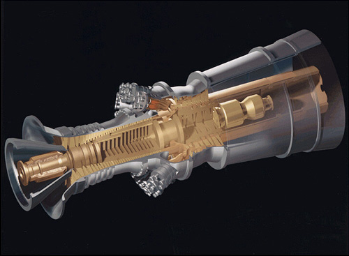
Gas turbine theory is not new to the world; in fact, Leonardo Da Vinci designed a reaction-type turbine. While nothing like the turbines of today, Da Vinci’s chimney jack’ used hot air rising from a hearth to turn an axial rotor attached to a roasting spit located over the fire. In this way, food on the spit turned without need for an attendant, harnessing the power of burning gases.
Early History
GE was one of the first modern companies to understand the power of turbine applications. High-profile projects like Niagara Falls (1918) and the Grand Coulee Dam project (1942) used GE turbines. The first gas turbine used to generate electric power in the US came from General Electric. It was a 3.5-MW unit installed at Belle Isle Station, Oklahoma City, OK, in 1949.
Expansion of Products
GE’s gas turbine division is now over a century old. It has advanced gas turbine jet engine design along with commercializing industrial gas turbines for the first time. GE turbines are also used for power generation. You can find them in nuclear power plants, combined-cycle gas turbine plants, and in steam turbine systems and boiler systems.
Introduction of Speedtronic Turbine Control
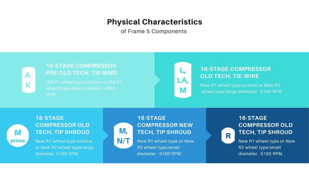
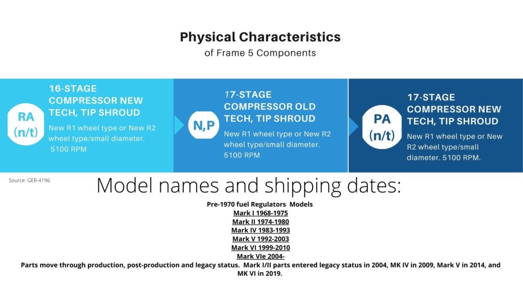
Beginning in the 1960s and continuing through the early 2000s, GE developed and sold sophisticated turbine control systems for their gas and steam turbines. These systems sold under the SPEEDTRONIC trademark name. Speedtronic systems started with the Mark I series, continuing through the release of the Mark VIe.
While each system had significant improvements, many Mark I and Mark II control systems are still in active use around the world today. The longevity of these systems is attibutable to GE’s adherence to specific gas and steam turbine control philosophies. These emphasize “safety of operation, reliability, flexibility, maintainability, and ease of use, in that order,” according to company documents. The gas philosophy maintains:
Gas Philosophy
- Single control failure alarms when running or during startup
- Protection backs up control, thus independent
- Two independent means of the shutdown will be available
- Double failure may cause a shutdown, but will always result in a safe shutdown
- Generator-drive turbines will tolerate full-load rejection without overspeeding
- Critical sensors are redundant
- Control is redundant
- Any control systems problems will be alarmed
- Standardize hardware and software to enhance reliability while maintaining flexibility
Steam Turbine Control Philosophy
Meanwhile, the steam turbine control philosophy states
- Provide clear separation between protection and control
- Controls comply with standard IEEE 122
- All control functions have a protection system backup
- A double set of steam valves will provide for major admissions including one set for protection and one for controls
- Classify protection (aka trips) by criticality.
- All important and vital functions use two out of three redundancy from sensor to actuator.
- A single control failure will not cause a shutdown but instead will cause a diagnostic alarm that is repairable online.
GE Speedtronic Turbine Control Systems
The Success of the Mark I and II
Mark I turbine control was originally released in the late 1960s. MKI’s averaged fifty PCBs (printed circuit boards) per control panel and offered three input loops, including a start-up, temperature, and speed loop. The Mark I worked on a “redundancy by association” philosophy. This meant while the system operated on one control, say temperature, it was backed up by the speed control. This gave the system a process fail-safe, although not to the same level of later, more sophisticated systems like the Mark IV.

The Mark II improved upon the Mark I by introducing solid-state integrated circuits and a new cabinet arrangement. The circuitry allowed the practical use of complex functions like combustion monitoring for the first time.
Control in both the Mark I and Mark II was powered by three loops (startup/speed/temperature) where whichever parameter requiring the least amount of fuel took precedence. The output of this minimum value gate was described as VCE (electronic control voltage.) This value determined how much fuel was used. Sequencing in the MKI used 28 VDC relays. The MKII used digital logic software for sequencing.
The Not-So Successful Mark III
Interestingly, very few units of GE’s Mark III system were ever sold. The few that made it through were only for the electro-hydraulic market, none for gas turbine control. However, this Speedtronic turbine control system had integrated circuits and was the first of the control systems to utilize microprocessors. It was also the first to offer triple modular control, but only for steam turbines. But it was used only on small and medium-sized turbine systems, limiting its market.
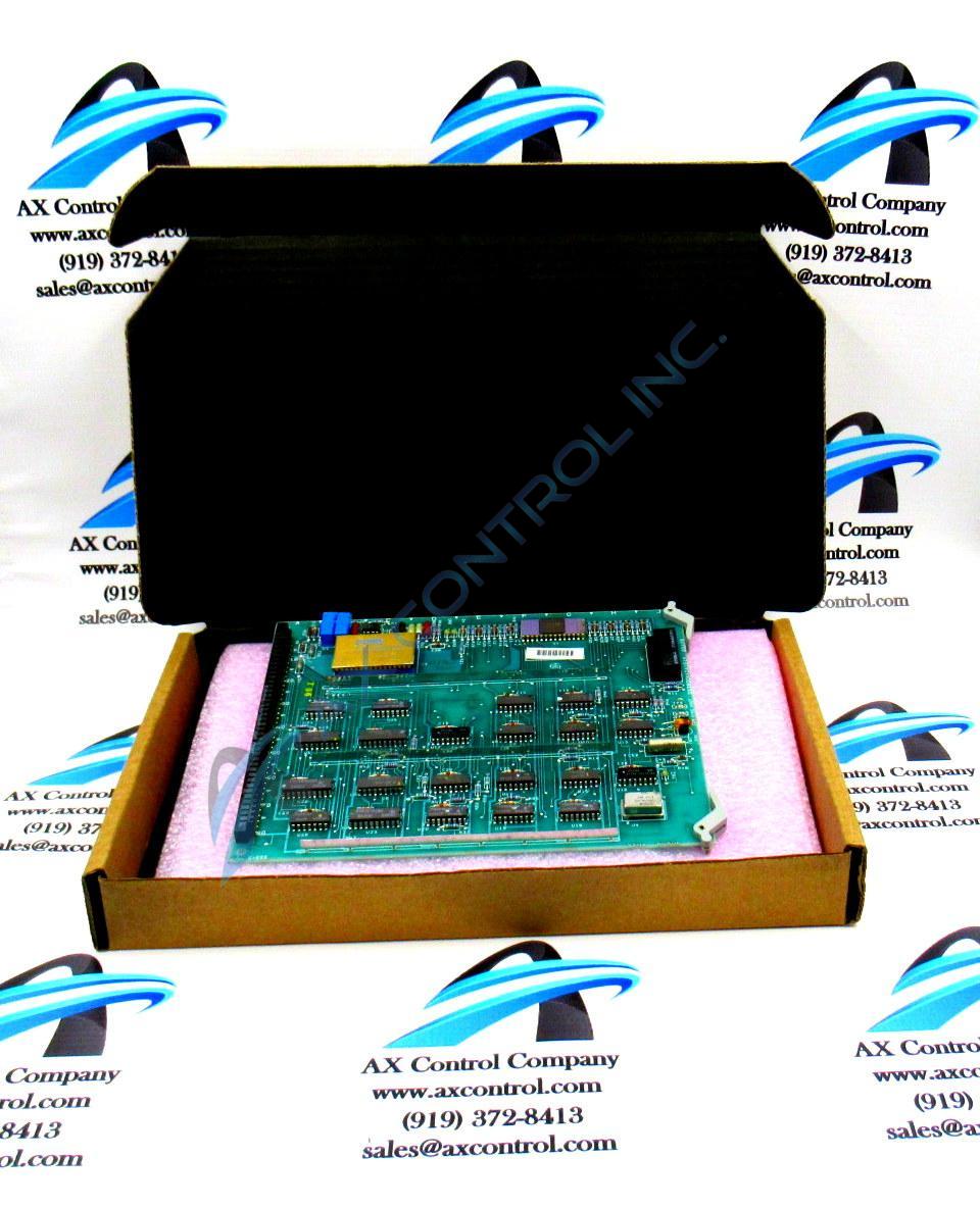
The Mark IV was the first GE turbine control system that offered triple modular redundant control for both gas and steam turbines. Also, this system offered digital control calculations. Digital control proved an improvement over previous analog systems. Mark IV communications used RS-232 or RS-485 transmission between the MKIV passive client and devices.
What is Speedtronic TMR Control?
Triple Modular Redundant control is a design with built-in redundancy. The system has three microprocessor controllers (in the case of the Mark IV, named <R>, <S>, and <T>). There is also a <C> communications microprocessor. The system has two-out-of-three voting, where each controller independently votes on conditions like temperature, over speed, valve position, etc. As long as two of the three agree, the system continues to run.
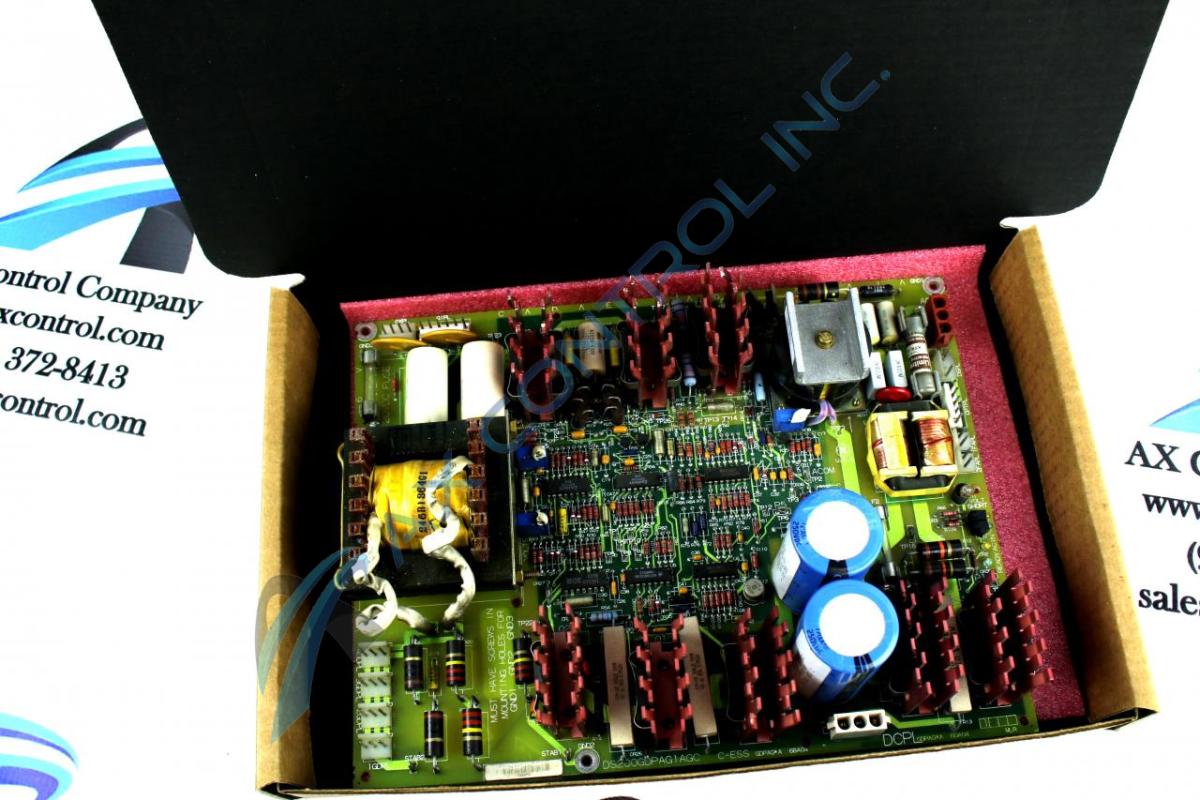
Mark IV
The Mark IV introduced a more user-friendly CRT operator interface that would display the state of logic functions and values. The display made it easier for operators to change values when needed, which could be done from the panel, vs. the previous method of finding the proper potentiometer on the correct board, and adjusting manually using a connected voltmeter.
Mark V
When the Mark V was introduced in 1991, it could be set up as either a TMR or a Simplex Speedtronic Turbine control system. One of the most significant improvements over the Mark IV was the change to software-implemented fault tolerance (SIFT), which helped fuel command signals to the digital servo remain synced. The MKV could be used for steam or gas turbines to drive compressors, pumps, or generators. Operator interface to the Mark V could be set up with an <I> Interface Data processor that consisted of a monitor, keyboard, and printer, or the system could be accessed via HMIs (human-machine interface.) The operator interface is typically set up to handle any communication with remote or external devices that might be necessary.
It is important to note that–in most cases–HMIs and/or the I/O are connected for data gathering and troubleshooting rather than for control purposes.
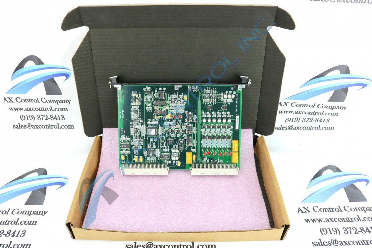
The Mark VI was designed by General Electric with a central Control Module that received inputs through termination boards using passive signal conditioning. This system could be designed in TMR or Simplex form and offered control, protection, and monitoring functions through the Control Module.
Are OEM upgrades available?
General Electric marketed the Mark VIe system as a “plug and play” upgrade migration from earlier legacy systems. The company suggested it was an OEM solution for the MKI, MKII, and MKIV.
The Mark VIe included many options, including single, dual, and triple-modular redundant controllers. The controllers paired with single, dual, and shared I/O. Because the Mark VIe had Ethernet capability, I/O could be local or remote.
While it is true the MKVIe offers extended capabilities to users, some of the Mark VIe components have now also been given legacy status by GE and are no longer supported by the OEM, which leaves them in the same situation as previous models. It’s likely the entire Mark VIe will become obsolete at some point. Additionally, parts remain available for previous systems for those who wish to keep their current configurations. Partnering with a reliable distributor with knowledgeable techs who can perform maintenance and repair on your components can also extend the lifespan of your system.
Many industries make use of the Mark VIe. This includes nuclear facilities, thermal and wind applications, as well as hydroelectric, oil, and gas systems. This is a Distributed Control System(DCS) with autonomous controllers distributed throughout.
How to Decode Your GE Part Number
GE Speedtronic Turbine Control boards followed a standard protocol for naming throughout most of their production, with some minor changes. Each series of boards typically had an original run, then had upgrades released later. In each series, the upgraded series will have a similar part number to the original board. For example, IS200ACLEH1A and IS215ACLEH1A are the same Mark VI board with the exception of the updated firmware available on the IS215board. Both cards function as Application Control Layer Modules.
When you’re running legacy systems, it may be important to understand how part numbers migrate from one production run to another in order to more easily locate useful manuals for your parts. While you may not be able to locate a manual for the IS200ACLEH1A mentioned above, the IS215ACLEH1A manual is still widely available and has sections that relate to both cards. Part number conventions are typically printed in the Renewal/Warranty Replacement section of hardware manuals.
Need a Speedtronic turbine control component repaired or replaced? Contact our team today.

You must be logged in to post a comment.