
GE’s Multilin Motor Management Relays provide protection and monitoring for three-phase motors. They also provide protection for their associated mechanical systems.
Introduction
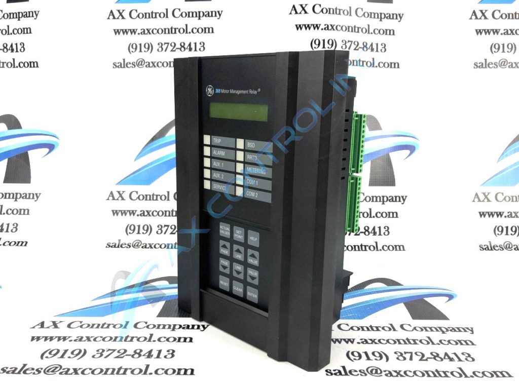
The GE Multilin 369 Motor Management Relay Series is designed with customizable relays. The units can protect three-phase motors and also offer monitoring applications.
Functional Summary Multilin 369
- Display: 40 Character, Alphanumeric LCD
- Status Indicators: 4 Output LEDs. Service LED, 5 other LEDs
- Keypad: 12-buttons, including Help Key.
- Interface: RS-232 comm port, Baud rate 120 to 19200
- Case: Corrosion and flame-retardent
- Digital Inputs: standard
- Analog Inputs: Available
- Current inputs: standard
- Ground CT inputs: standard
- Ports: 3 x RS485, Baud rate 1200 to 19200
- RTD Inputs: available
- Profibus Port: available
- Backspin detection: available
- Fiber Optic Data Link: available
- Voltage Inputs: available
Protective Functions Multilin 369
Motor protection including:
- Standard phase overload curves
- Programmable (custom) overload curves
- current unbalance
Management functions including:
- Pre-trip data, to 40 events
- starts per hour
- time between starts
- mechanical stall and jam
- statistical data
- backspin detection
- flash memory
- power metering (optional)
Technical Specifications Multilin 369
- Control power: LO = 20 to 60 VDC, 20 to 48 VAC at 50/60 Hz, HI= 50 to 300 VDC, 40 to 265 VAC at 50/60 Hz
- Power: Nominal: 20 VA, Max 65 VA
- Fuse: T 3.15 Amp H 250 V, Timelag high breaking capacity
- Operating Range: -40 to +60 Celsius
- Operating Range w/Profibus: +5 to +60 Celsius
- Humidity: up to 95%, non-condensing
- IP50
- Overvoltage Cat. II
Introduction
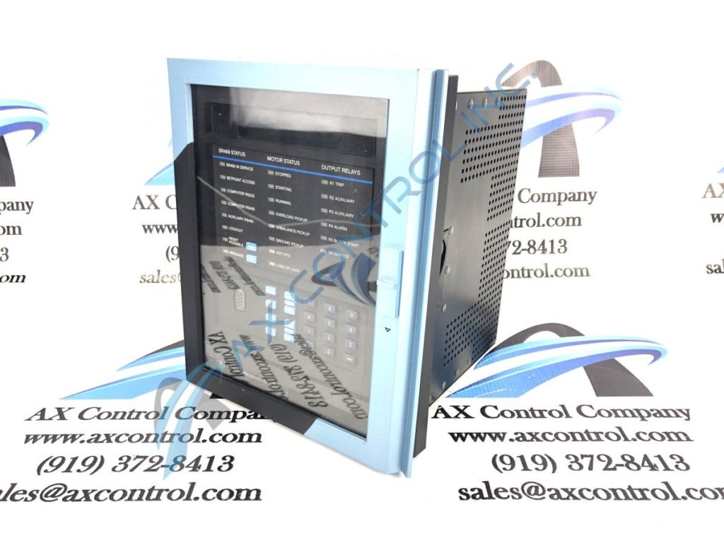
The GE Multilin 469 Motor Management Relay is used to manage and protect motors of many HP ratings.
Functional Summary Multilin 469
- Display: 40 Character, Alphanumeric LCD
- Status Indicators: 6 Output LEDs, 8 Motor Status LEDs, 8 other LEDs
- Keypad:Alphanumeric with Help button, plus +/- value keys. Message toggle keys. Enter, Menu, Escape, and Reset Key.
- Interface: RS-232 comm port
- Case: draw-out, IP40-X
- Digital Inputs: 9 opto-isolated
- Analog Current Inputs: specifications vary
- Differential Current Inputs: Primary, 1 to 5000 A. Secondary, 1 A or 5A.
- Ground CT inputs: Primary, 1 to 5000 A. Secondary, 1 A or 5 A.
- Phase Current Inputs: Primary 1 to 5000 A. Secondary, 1 A or 5 A.
- RTD Inputs: 3 wire RTD types
- Voltage Inputs: 273 VAC full scale
- Ports: 2 x RS485
- Modbus: Modbus RTU/half-duplex
- Ethernet: Available
- DeviceNet: Available
- Backspin detection: Restart Block can act as a backspin timer
Protective Functions Multilin 469
Motor protection including:
- Overload Pickup using RTDs
- Overload Curve
- Short Circuit Trip
- Ground Fault
- Unbalance Alarming
- Acceleration Trip
- Stopped/Running Cooling Times
- Stator and Bearing RTDs
- Unbalance bias of thermal capacity and K factor
- Hot/cold curve ratio
Management functions including:
- Starts per hour
- Time between Starts
- Enable Start Inhibit
- Mechanical jam
- Remote Switch
- Vibration & Pressure Switches
- Remote Start/stop
- Breaker failure
Technical Specifications Multilin 469
- Control Power: LO = 20 to 60 VDC, 20 to 48 VAC at 48 to 62 Hz, HI= 90 to 300 VDC, 70 to 265 VAC at 48 to 62 Hz
- Power: 45 VA (max) 25 VA (typical)
- Fuse: 2.50 A 5 x 20 mm SLO-BLO HRC Littelfuse, high breaking capacity
- Operating Range: -40 to +60 Celsius
- Humidity: up to 90%, non-condensing
- Altitude: up to 2000 m
- Pollution degree: 2
- IP: check case
- Overvoltage: check case
Other differences you may want to consider. While the Multilin 369 can be used for small or medium induction motors and induction motors with a cyclic load, they cannot be used for large induction motors or induction motors via VFD as the 469 Multilin can. Additionally, the 469 offers synchronous motor protection that the 369 doesn’t have.
Also keep in mind the 469 has trip/close coil supervision. The 369 doesn’t offer that.
Both Multilin options are extremely versatile. Since they both offer a wide operating temperature range (-40 C to +60 C) they are suitable for a number of climate conditions. So even if your factory has to deal with Canadian cold or Australian heat, these motor management relays should work well inside its walls.
Have more questions? Se our GE Multilin FAQs blog.

You must be logged in to post a comment.