PID, or Proportional-Integral-Derivative, is a control method used in industrial automation. This tutorial will clear up some misconceptions about this term.
PID controllers have been used in some form since the early 1900s. They were originally based upon a 19th-century governor speed limiter. Early PID-like controllers were used to automatically steer ships for the US Navy. These controllers were developed by Nicolas Minorsky. He focused on designing a system that would provide stability against both small and large disturbances.
Today, nearly 95% of closed-loop industrial systems use PID control.
PID is essentially a feedback loop control made out of code. It can sometimes be made from the hardware. PID, which stands for Proportional Integral Derivative, is made up of three separate parts that have been joined. However, in some situations, all three parts of the control are not needed. As a result, you can have P control, PD control, or PI control.
Explanation of PID Parts
- P=Proportional. The proportional component of PID allows for the correction of a value in proportion to an expected error. For example, if in building a system, you know your battery will slowly discharge and likely provide less power to your system, you can write a (P) value to correct for this known value error to control your output accordingly.
- I=Integral. The integral component of PID essentially takes up the slack left by (P.) It is the running sum of previous errors. What this means, is whatever small amount of error left over after (P) is accounted for is taken care of by (I.)
- D=Derivative. The last bit of the PID code is supposed to predict the future. The derivative component finds the difference between any current error and any previous error and adjusts the output accordingly. Control loops that include a (D) component can significantly more time to ‘dial in’ due to the complex nature of the derivative.
PID frequencies are relative to the bandwidth of the servo or process, where the Integral term is most effective at low frequencies, Proportional at moderate frequencies, and Differential at higher frequencies. PID is more common in process control where pressures, temperatures, position, etc need to be optimally controlled.
The Effects of PID
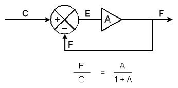
In order to properly discuss the effects of PID, we must first look at a basic closed-loop servo and the equation for a closed-loop response. In the Sept. 1990 issue of Motion Control, this block diagram of a basic servo and its response formula were published.

In the top diagram, we have the element (A). The action of the summing junction is to subtract the feedback signal (F) from the input (C) with the result known as the error signal (E)=C-F.
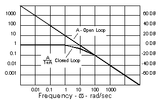
The Bode diagram (below) shows how open-loop gain A in an amplifier/motor combination typically experiences a decrease of amplitude by a factor of 10 for every factor of 10 increase in frequency.

The net effect is that A is also A -90° since it has a gain factor of A and a phase lag of 90°. This closed-loop response [F/C = A/(1+A)]
As A’ approaches 1 on the Bode diagram (at 10 rad/sec in the example) the denominator becomes 1+1 -180°=1-1=0 and F/C becomes infinite. As a result, severe oscillations can occur. But in order to maintain a stable system, the denominator must not be allowed to approach zero. A commonly accepted design goal is for A’ to have -135° of phase shift or less (45° of phase margin) This will result in a 25% overshoot of the closed-loop system in response to small step inputs.
As the phase margin gets larger, the amount and number of overshoots diminish. In addition, as the phase margin gets smaller, the overshoots get larger and will “ring” for longer periods. Finally, a sustained oscillation will occur.
Conclusion
PID provides phase compensation to improve the performance of the servo, using coding to create a closed-loop servo with a wider bandwidth and a greater gain (thus greater accuracy) within that bandwidth. If no velocity loop exists, PID is a good alternative.
Take a look at our current Woodward servo position controller stock for real-world examples of these machines.


You must be logged in to post a comment.