Designing with FPGAs

What does FPGA Stand For?

FPGAs, or field-programmable gate arrays, are more complex than typical integrated circuits. “FPGA” stands for field-programmable gate array. The higher number of I/O pins on an FPGA requires forethought in design and layout and considerations in regard to system needs.

These integrated circuits are more complex than your average IC. Reconfiguration is possible with FPGAs. An FPGA can function as a GPU (Graphics Processing Unit) then used later as a processor or video encoder. FPGA hardware and circuits allow many reconfigurations. This is not possible with standard chips.

Reconfiguration occurs through gates or flip-flops, using configurable logic blocks, or CLBs. Just remember there are thousands of CLBs on a typical FPGA.

What’s the difference between FPGAs and CPLDs?

A CPLD, or Complex Programmable Logic Device, is based on EEPROM architecture. It typically contains only a few thousand logic blocks and may have significantly fewer. FPGAs have up to 100K logic blocks and is a RAM-based digital logic chip.

How to use FPGAs

Field programmable gate arrays are versatile. Some common uses include:

  • As a graphics processing unit
  • As part of an SDR transceiver
  • To upscale video

Also, a wide range of applications use FPGAs. This includes video, military, and industrial applications.

How Do FPGAs Work?

FPGAs act as parallel devices where each independent task has been assigned to a specific and independent part of the chip, which is created out of programmable silicon chips that include programmable logic blocks that have been surrounded by I/O blocks. You can visualize this as a downtown city block with many independent businesses located in individual buildings; each business goes about its own work without any impact on the performance of the businesses around it.

What Are the Advantages of FPGAs?

FPGAs offer many advantages, not the least of which is their flexibility and functionality. For example, advantages include

  • Ability for adaptation after delivery if updates are required in programming
  • Accelerated prototyping because hardware development is part of the IP core.
  • Cost-effective software solutions for complex tasking via parallelization and adaptation to the application.
  • Real-time OS calculations are ideal for time-critical systems.

Budget for Power

Your board should work consistently with a 20% margin above and below the operating frequency and with a 5-10% margin on voltage and temperature. These margins can be achieved by keeping trace lengths as short as possible, by reducing the number of vias on your board that will impede your signal quality, and by ensuring there is a good return current path for every signal transmission path.

FPGAs are used as part of a PCB design.
FPGAs can be programmed to carry out one or more logical operations.

It is also important to make sure you have sufficient power supplies to handle your system needs. FPGAs have multiple power supplies of differing voltages. Each of these power supply voltages should have its own power budget within your design.

Properly Clock FPGAs the first time

Most FPGAs use a global clock pin that distributes the clock throughout the chip, and other pins that confine the clock to particular regions. These embedded clock management systems are powerful and facilitate the design. But the improper choice of a clock pin will create a system-level design issue that will allow the board to work most of the time, but not all of the time. This type of marginal error is extremely difficult to find, debug, and fix. It is easier to avoid than to fix later.

Find out more information about FPGAs and other integrated circuits in our printed circuit board tutorial.

We maintain lots of ready-to-ship PCBs, especially for GE Speedtronic Turbine Control Systems. Talk to our team today.

Resistor Color Code Quick Guide

Closeup of a GE 531X Power Supply Board with banded resistors.
GE Motor Field Power Supply Board uses banded resistors.

If you’ve ever had to figure out a resistor color code–the value, tolerance, and wattage of multiple resistors, you know how mentally exhausting it can become. Mnemonic devices aside, sometimes it’s simpler to have a visual guide to help. 

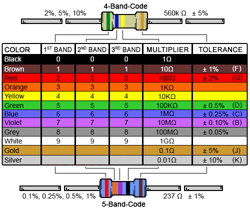
This tool is designed to decode color-banded axial lead resistors with four or five bands.  You can use the number of bands and the colors along with the charts below to determine the value and tolerance of the resistors.

Feel free to make use of our favorite Resistor Color Code Guide, available below.  Right-click for a higher-definition view.


Resistor Color Code chart

How to Read Resistor Color Code

Four banded resistors have two bands for resistance, one multiplier band, and one band for tolerance. Five band resistors have an extra color band added to the first and second resistance digits. This gives you a more precise reading. Everything else shifts to the right, so the fourth band becomes the multiplier and the fifth becomes the tolerance.

Super simple, right?

Also, remember to take a good look at the body of your larger resistors to see what information is available to you. Many resistors are marked with their resistance value, tolerance, and wattage resistance if their body is large enough.

British Standard Code

Larger power resistors may use BS1852 British Standard Code, which uses suffix letters to replace part of the number to minimize misreading the position of the decimal point. This system uses “K for thousands or kiloohms and the letter M for millions or megaohms. R is used to denote a decimal point for resistor values of less than one. Thus:

  • 0.01Ω = R010 or 0R01
  • 1.0Ω=1R0
  • 24.9Ω=24R9
  • 4.7KΩ = 4K7
  • 470KΩ = 470K or 0M47
  • 1MΩ = 1M0

Tolerance Letters

Tolerance letters take the place of written out percentages. Tolerances also use K and M, so be sure when reading the code to know which letter refers to resistance value and which to tolerance.

  • B = 0.1%
  • C = 0.25%
  • D = 0.5%
  • F = 1%
  • G = 2%
  • J = 5%
  • K = 10%
  • M = 20%

Finally, remember the first band is typically the one closest to a lead, while the tolerance, which is always gold or silver, is the last band. This will help you understand which way to “read” the bands.

Carbon resistors are the most common type of resistor used within electronics. Carbon resistor color code is the standard resistor color code shown on this page.

And if there’s ever any doubt, you can measure resistance with a multi-meter.

Answers to a few commonly asked questions about resistors

What are the different types of electrical resistors?

  • Wire Wound Resistor–constantan or manganin wire wound around an insulating cylinder.
  • Metal Film Resistor–carbon or metal deposited as a thin film on to an insulating core.
  • Carbon Composition Resistor–mainly made of carbon clay covered with a plastic case. Very temperature sensitive.
  • Carbon Film Resistor
  • Variable Resistor–resistance value can be adjusted. A rheostat is one example.
  • Varistor–non-linear component where resistance changes with applied voltage.
  • Thermistor–resistance value changes with a change in temperature
  • Light Dependent Resistor–resistance varies depending on intensity of light.

Does a resistor consume energy?

Yes. As they do their primary job (control the flow of energy) they also consume some of the energy. A good example of this is the filament of a traditional light bulb, which lights up because it resists the flow of energy moving through it. But it also puts out heat (as anyone who has tried to change a burning light bulb can attest.)

Do resistors have polarity?

Current flows from positive to negative according to current direction. So resistors on their own do not have polarity in the sense they can connect to a circuit in either direction. But current can only flow in a single direction.